DA20-C1 Flight Manual
Supplement 8
Doc # DA202-C1 April 16, 2009 Page S8 - 3
7. DESCRIPTION OF THE AIRPLANE AND ITS SYSTEMS
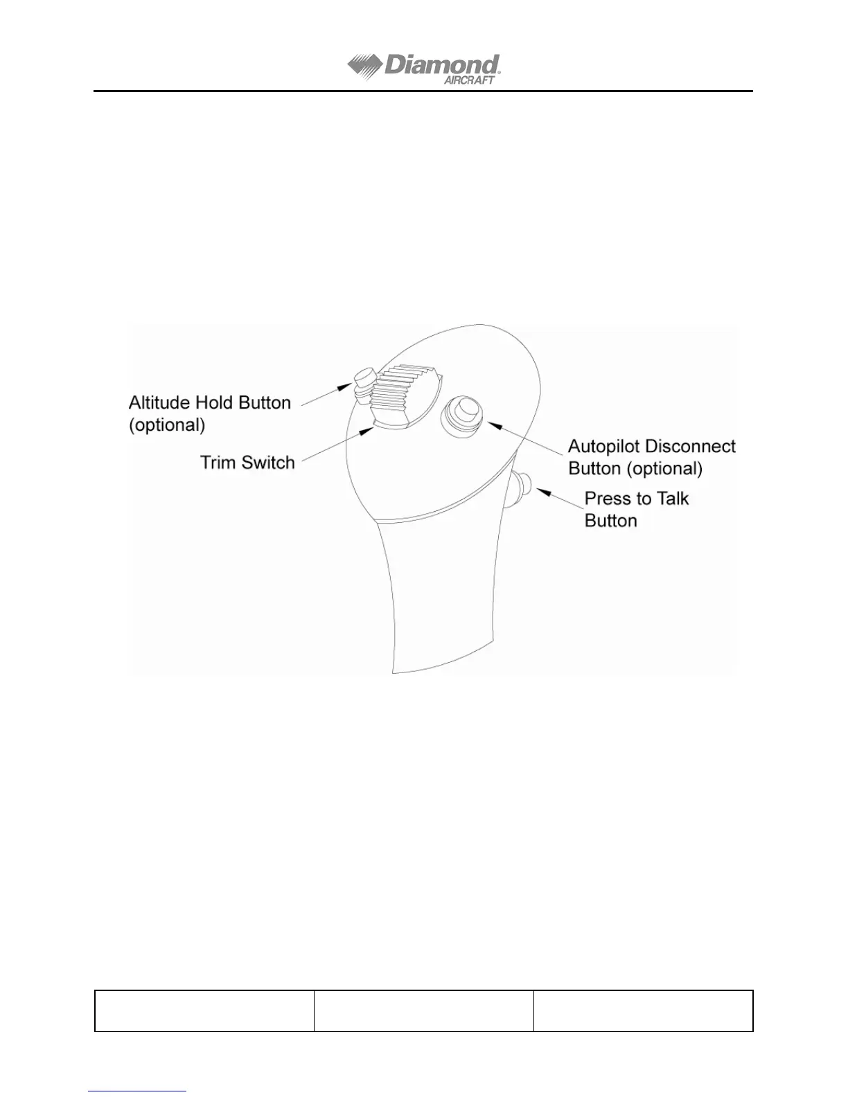
Trim Switches are located on top of each Control Stick, aft of centre. The switches are
positioned so that they can be easily operated by thumb. Forward movement of either switch
gives nose down trimming and aft movement of the switch gives nose up trim. The trim
switches control electrical relays that supply electrical power to the electric pitch trim motor. If
the switches are operated in opposing directions at the same time, the trim motor will not
operate. Operation of the trim switches in the same direction and at the same time will cause
the trim motor to operate in that direction.
Figure 1. Control Stick Grip (Left Hand Shown)
8. HANDLING, PREVENTATIVE AND CORRECTIVE MAINTENANCE
Service and maintenance of the Stick Mounted Trim Switches shall be performed according to
the Diamond Aircraft Maintenance Manual (Document number DA201-C1).
Revision 24 DOT Approved