Dobot M1 User Guide 6 Operation
Issue V1.3.4 (2019-05-23) User Guide Copyright © Yuejiang Technology Co., Ltd
113
The Dobot M1 has been powered on.
The Dobot M1 has been connected to a PC successfully.
The Dobot M1 has been connected to an emergency stop switch.
The Dobot M1 has been connected to a DB62 external expansion board.
Procedure
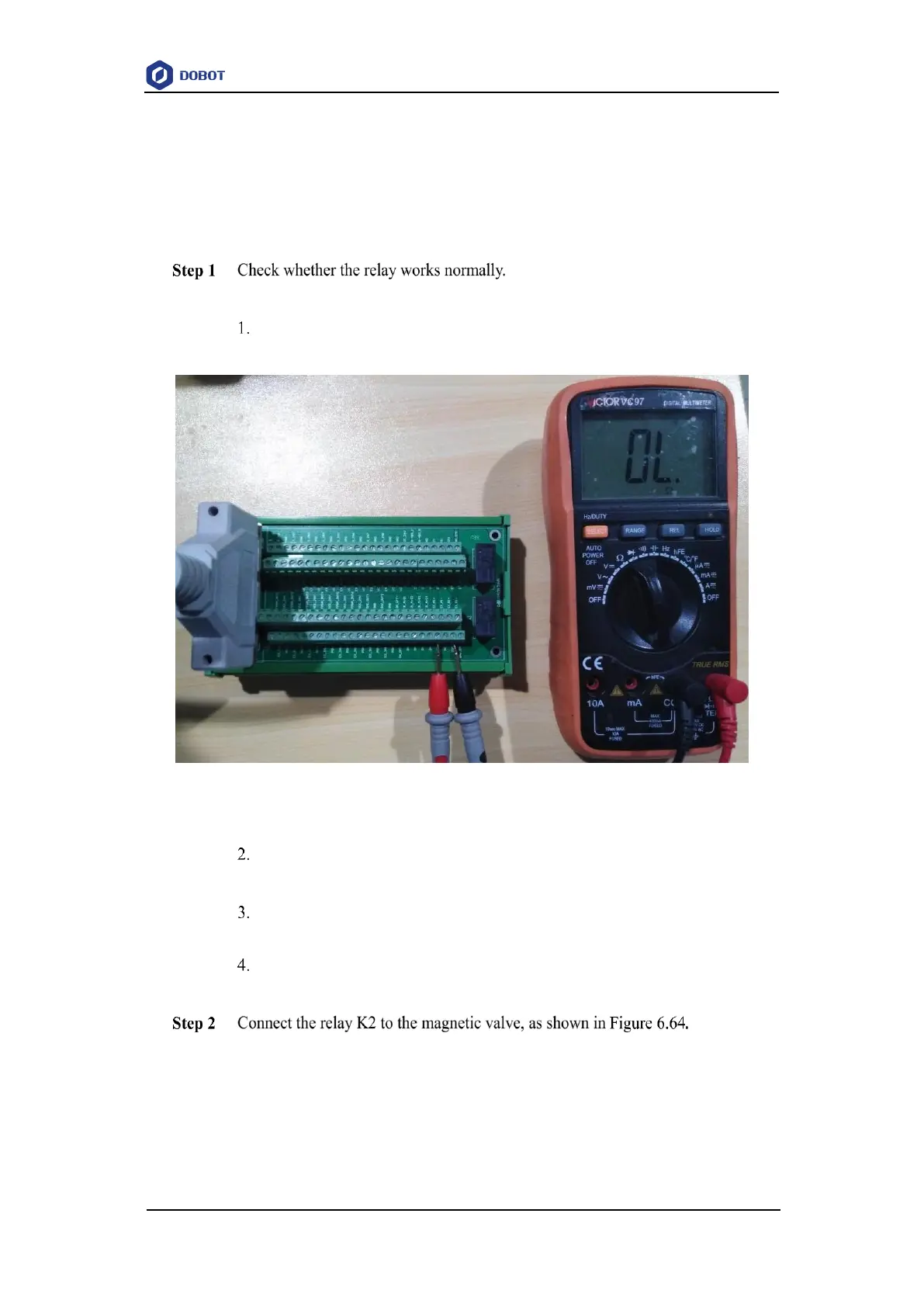
Take the relay K2 as an example.
Set the multimeter to Continuity mode and connect one probe to COM2
interface, and connect the other probe to NC2 interface.
Figure 6.63 Using multimeter to test relay
Click 24V of OUT10 on the Output pane of the I/O Assistant page.
If a tone is emitted, the Normally-Closed function works normally.
Connect one probe to COM2 interface, and connect the other probe to NO2
interface.
Click 0V of OUT10 on the Output pane of the I/O Assistant page.
If a tone is emitted, the Normally-Open function works normally.
When the status of EX_OUT10 is high level, the magnetic valve will not work.
While the status of EX_OUT10 is low level, the magnetic valve will work.