Dobot M1 User Guide 2 Introduction
Issue V1.3.4 (2019-05-23) User Guide Copyright © Yuejiang Technology Co., Ltd
9
Joint coordinate system: The coordinates are determined by the motion joints.
Dobot M1 contains four joints.
J1, J2, and J4 are the rotating joints, which are located and oriented in the horizontal
plane. And their axes are parallel to each other. The positive direction of these joints
is counter-clockwise.
J3 is the moving joint, which is used for the movement of the end effector in the
perpendicular plane. The positive direction of J3 is vertical upward.
Cartesian coordinate system: The coordinates are determined by the base.
The origin is the axes center of the motor of Rear Arm where Rear Arm is dropped
to the bottom of the Z-axis screw.
The direction of X-axis is perpendicular to the base forward.
The direction of Y-axis is perpendicular to the base leftward.
The direction of Z-axis is vertical upward, which is based on the right-hand rule.
The R-axis is the attitude of the end center relative to the origin of the robotic arm,
of which the positive direction is counter-clockwise. The R-coordinate is the sum of
the coordinates of J1, J2, and J4.
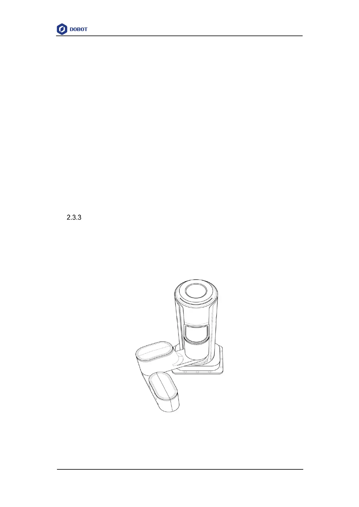
Arm Orientation
With two types of the arm orientation (lefty hand orientation and righty hand orientation),
Dobot M1 can move to nearly any position and orientation within a given work envelope. You
need to specify the arm orientation when Dobot M1 is moving. If you fail to do so, Dobot M1
may move following an unexpected path, resulting in interference with peripheral equipment.
The arm orientations are shown in Figure 2.5 and Figure 2.6.
Figure 2.5 Righty hand orientation