Dobot M1 User Guide 6 Operation
Issue V1.3.4 (2019-05-23) User Guide Copyright © Yuejiang Technology Co., Ltd
100
point F and point G, you need to save point G. For details, please see 6.1.3 Saving Point
in ARC Mode. The arm orientation of point F must be the same as that of point G and
point H.
From point H to point I (6->7): The trajectory looks like a door. So JUMP mode is
required. You need to set Height and Limit.
From point I to point J (7->8): The trajectory is a circle. So CIRCLE mode is required.
Besides point I and point J, you need to save point K. The method to save point in CIRCLE
mode is the same as that of ARC mode. The arm orientation of point I must be the same
as that of point J and point K.
Example of the External Drive
The current of the digital output supports 2mA without additional power, whereas the
maximum current of the digital output supports 3A with an additional power. Because the
default drive capacity of the Dobot M1 is insufficient. When the control device that is
connected to the I/O interface needs to provide a sufficient drive capacity, you must have an
external drive to increase the drive capacity.
Figure 6.48 shows the connection between the I/O interface and control device without
additional power.
VCC_24V is the output voltage of the I/O interface of Dobot M1. OUTx is the output of
the I/O interface (assuming that OUT0 and OUT1). Please select the proper outputs based on
site requirements. For details, please see 4.3 Interface Description.
GND
24V
MCU
•
•
10k
•
Magnetic
Valve
VCC_24V
(I/O)
•
OUTx
(I/O)
Internal Circuit
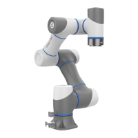
Figure 6.48 Connection between I/O interface and control device by default
Figure 6.49 shows the connection between the I/O interface and control device with an
additional power. The red box in Figure 6.49 shows the external drive circuit. You can make an
external drive circuit to meet the drive capacity requirements according to Figure 6.49.
VCC_24V is the output voltage of the I/O interface of Dobot M1. OUTx is the output of
the I/O interface (assuming that OUT0 and OUT1). GND is the ground of the I/O
interface. Please select the proper outputs based on site requirements. For details, please
see 4.3 Interface Description.
24V is the external voltage. PGND is the ground corresponding to the external voltage.