Dobot M1 User Guide 6 Operation
Issue V1.3.4 (2019-05-23) User Guide Copyright © Yuejiang Technology Co., Ltd
101
GND
24V
MCU
•
•
10k
• •
OUTx
(I/O)
•
10k
10k
GND
(I/O)
•
VCC_24V
(I/O)
PGND
(External)
24V
(External)
Internal Circuit
Magnetic
Valve
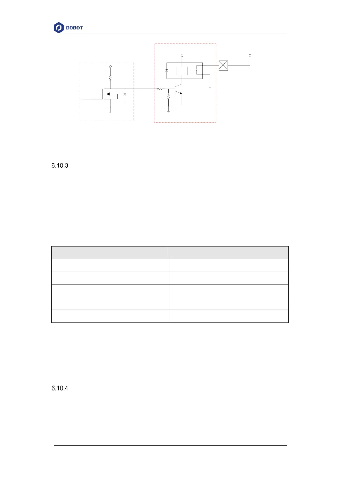
Figure 6.49 Connection between the I/O interface and control device with an external drive
Example of Switching the Arm Orientation at the Same Point
In MOVJ or JUMP mode, if the two points are the same, only different in arm orientations, J1
or J4 may be limited when the Dobot M1 is moving, resulting in an alarm generated. You need to
modify and resave the point for which the alarm is generated, and then clear the alarm manually.
The R-coordinate is the sum of the coordinates of J1, J2, and J4. The terminal posture relative
to the origin stays constant when moving the Dobot M1. Table 6.12 lists how to calculate each Joint
coordinate after switching the arm orientation at the same point.
Table 6.12 Joint coordinate calculation
As shown in Table 6.12, If the J1-coordinate is 10° and the J2-coordinate is 90° before
switching the arm orientation, the J1-coordinate will change to 100° after switching, resulting in a
limitation alarm. In the real application scenario, if the two successive saved points are the same,
only different in arm orientations, please notice the coordinates of J1 and J4. You can calculate the
coordinates of J1 and J4 according to Table 6.12, in order to avoid generating a limitation alarm.
Example of TCP/IP Control
TCP/IP control means that external equipment controls a robot arm by sending commands with
TCP/IP. External equipment is the client, and main controller or M1Studio is the server, as shown
in Figure 6.50. Moreover, the IP address of the client and server must be in the same network
segment.