Dobot M1 User Guide 6 Operation
Issue V1.3.4 (2019-05-23) User Guide Copyright © Yuejiang Technology Co., Ltd
112
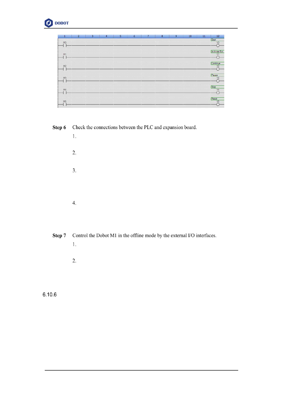
Figure 6.62 PLC program
Select the corresponding IP address from the serial drop-down list on the upper
left pane of the M1Studio page and click Connect.
Select Tools > I/O Assistant.
The I/O Assistant page is displayed.
Trigger Y0 on the GX Works3 page, and observe the changes of DIN 10 on the
I/O Assistant page.
If the voltage of DIN 10 shown on the I/O Assistant page is changed, it
indicates that the connection is correct. Otherwise, please reconnect it.
Check DIN 11 - DIN 15 according to 3 and Figure 6.59.
It is recommended that DIN 11 is checked at last, since DIN 11 is triggered, the
Dobot M1 activates the external I/O control function, and then when DIN 15 is
triggered, Dobot M1 will run in the offline mode.
Trigger Y1 on the GX Works3 page, the Dobot M1 will activate the external I/O
control function.
Trigger Y5 and the Dobot M1 will run in the offline mode.
If stopping the Dobot M1 running in the offline mode is required, please trigger Y4. At this
point, the Dobot M1 stops offline running, while the external I/O control remains in force. If
continuing the Dobot M1 running in the offline mode is required, please trigger Y5 directly.
Example of Relay Connection
DOUT9 and DOUT10 are used to control the relay K1 and K2 respectively, which are internal
encapsulated interfaces. If you have to use a relay, you can use the COM, NC, NO interfaces directly
on the external expansion board after the external expansion board connects to the Dobot M1. If you
have to test the relay K1 and K2, you can debug OUT09 and OUT10 on the M1Studio > I/O
Assistant page.
This topic takes a magnetic valve as an example to describe how to connect to a relay.
Prerequisites