Dobot M1 User Guide 6 Operation
Issue V1.3.4 (2019-05-23) User Guide Copyright © Yuejiang Technology Co., Ltd
110
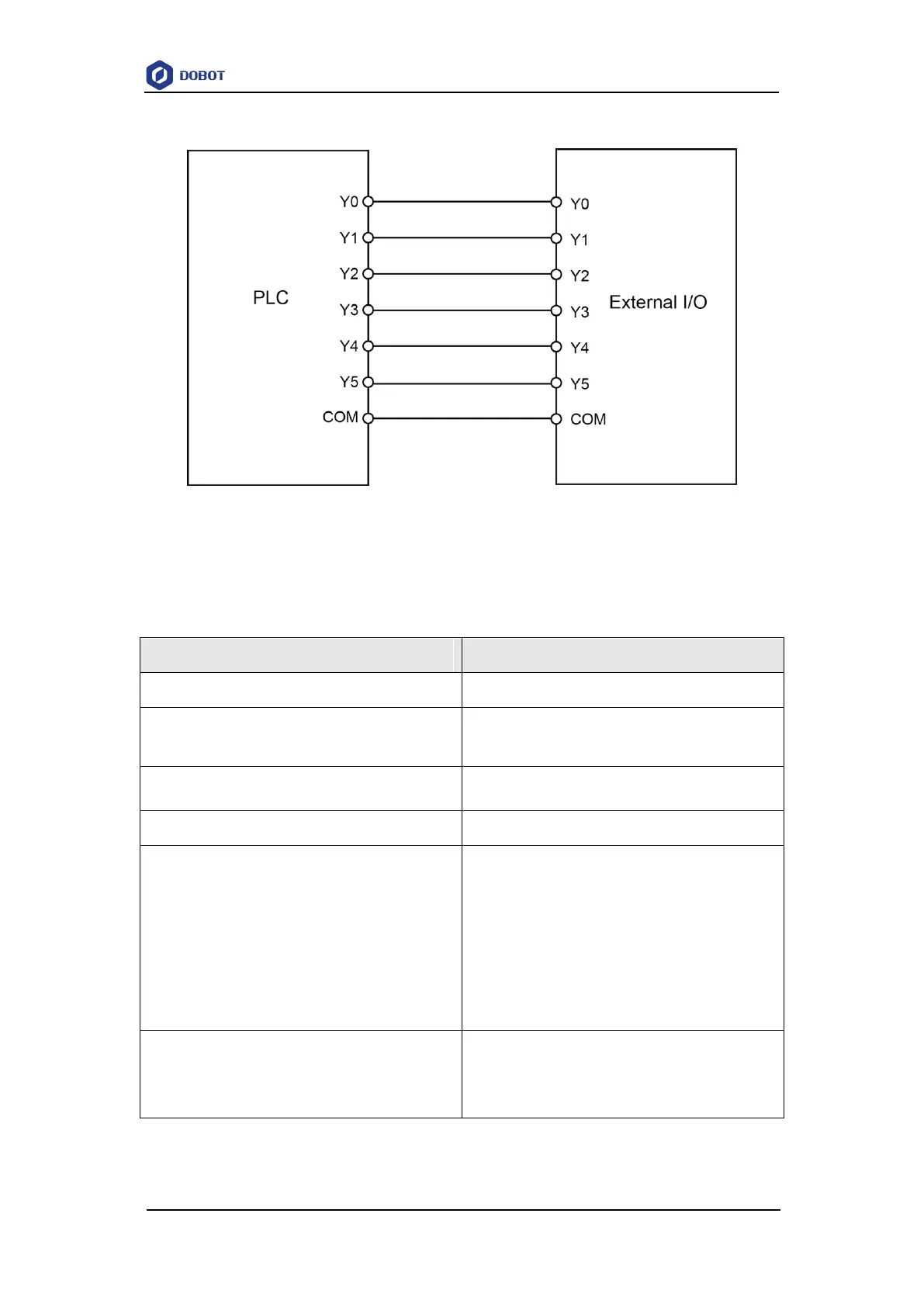
Please use the wires of which the size is from 20 AWG to 24 AWG for connections.
Figure 6.59 Connection between PLC and expansion board
Table 6.13 lists the definitions of external expansion I/O interfaces from DIN10 to DIN15.
Table 6.13 DIN10 - DIN 15 interfaces definition
External I/O control signal. Namely, the Dobot
M1 activates the external I/O control function
After this signal is triggered, the Dobot M1 will
stop offline running while the external I/O
control will remain in force. At this point, you
can use the M1Studio to control the Dobot M1
in the Dobot mode or trigger DIN 15 to make
the Dobot M1 run in the offline mode again
Start signal, for running in the offline mode
Before triggering this signal, please trigger
DIN 11