Dobot M1 User Guide 4 Electrical Specifications
Issue V1.3.4 (2019-05-23) User Guide Copyright © Yuejiang Technology Co., Ltd
26
4.3.1.1 AC Input Interface
NOTICE
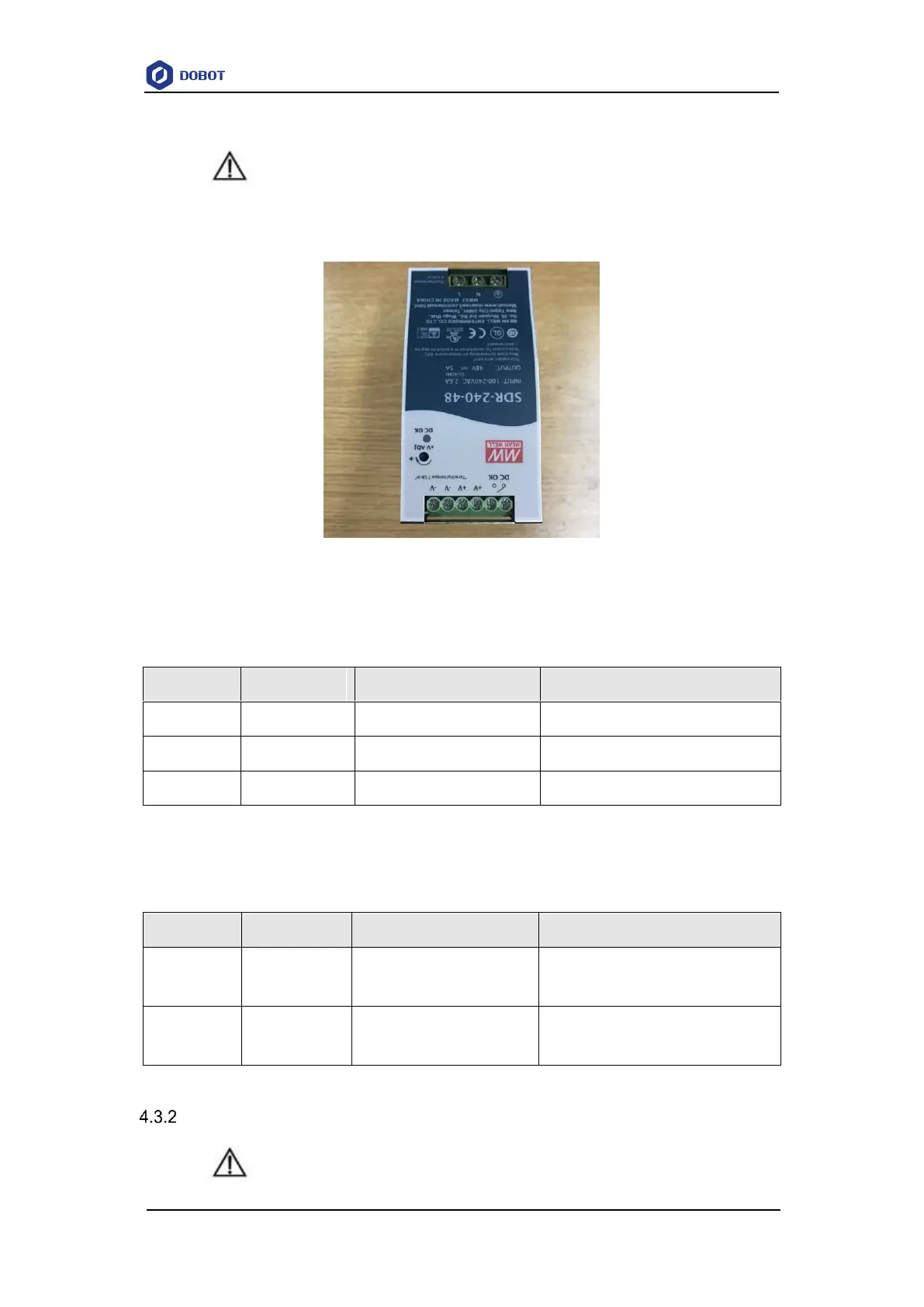
Figure 4.3 shows the power adapter. For details on how to connect the Dobot M1 to the
power adapter, please see 5.2.1 Connecting Power Supply.
Figure 4.3 Power adapter
Table 4.3 The power adapter input interface description
4.3.1.2 DC output Interface
Table 4.4 The power adapter output interface description
Positive electrode of the DC
power
Negative electrode of the DC
power
Body I/O Interface
NOTICE