19 GPIO and Audio Pin-Out Schema
• This section provides information on the IMB Certainty revision E boards and their GPIO
and Audio pin-outs. To view a full list of technical specifications for the IMB Certainty,
please see document # CRT.OM.001118.DRM (contact Doremi Tech Support to receive
it).
19.1 GPIO Pin-Out
19.1.1 GPI Pin-Out Information
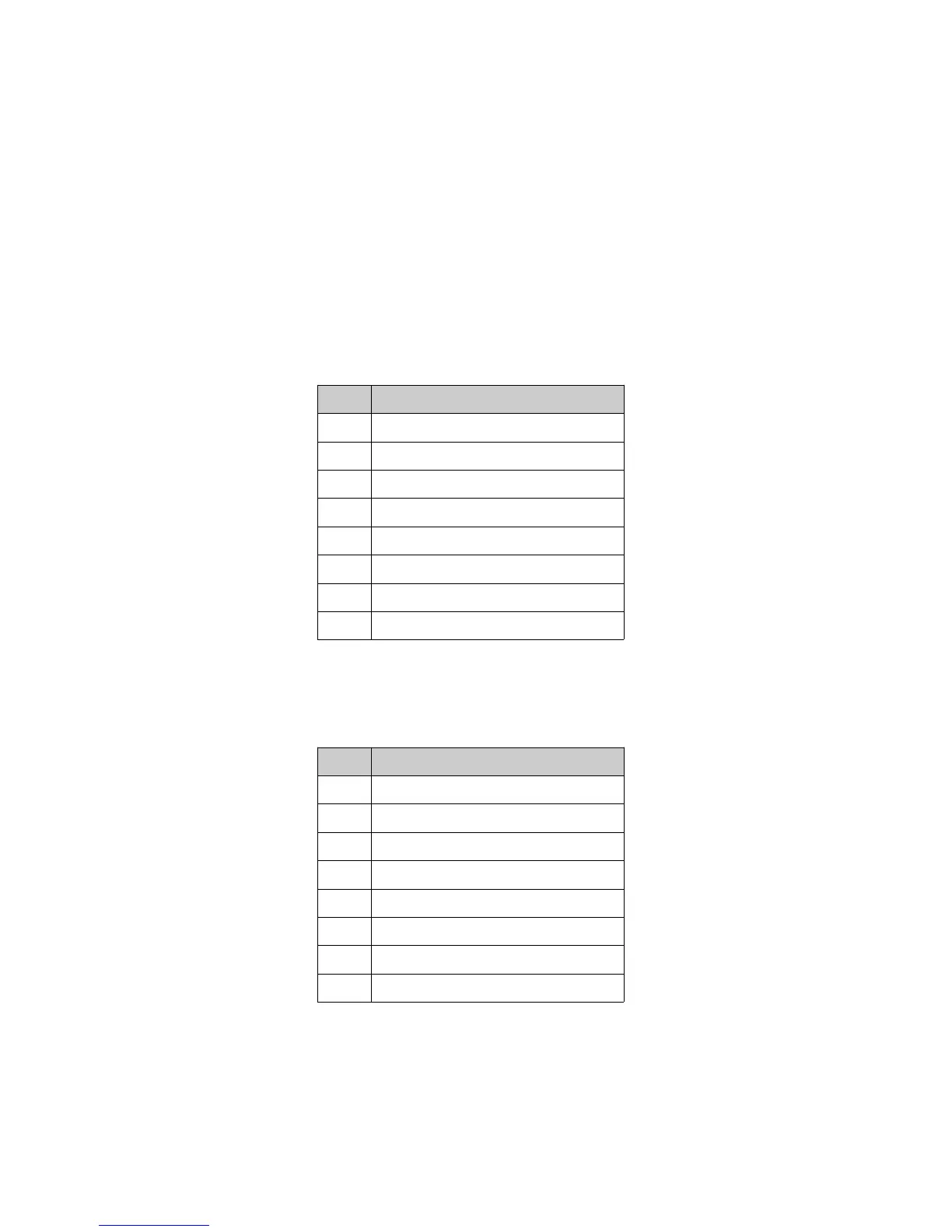
• 4 GPI on RJ45 Connectors (see Table below):
Pin # Signal
1 GPI 0+
2 GPI 0-
3 GPI 1+
4 GPI 2+
5 GPI 2-
6 GPI 1-
7 GPI 3+
8 GPI 3-
19.1.2 GPO Pin-Out Information
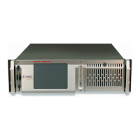
• 8 GPO on RJ45 Connectors (see Table below):
Pin # Signal
1 GPO 0
2 GPO 1
3 GPO 2
4 GPO 4
5 GPO 5
6 GPO 3
7 GPO 6
8 Ground
_____________________________________________________________________________________
SHV.OM.001293.DRM Page 115 Version 1.3
Doremi Cinema LLC Confidential