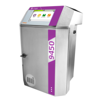
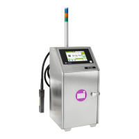
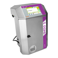
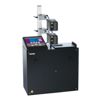
Servicing: 9040, 9040 IP65, 9040S
A36951-C.doc
119/236
1. Disconnect quick-connect self-sealing pressure connector(s) and connect flushing
connector(s) (see hydraulic diagram on following page).
2. Connect the drain unit quick-connect connector on the ink circuit pressure outlet and
place the second drain unit tube in an empty container to accumulate waste. (minimum
quantity of 5 liter container is recommended).
3. Drain the ink tank, the viscometer circuit (the viscometer + the constant-level tube) and
the main filter (leave the filter cartridge installed).
4. Pour two liters of additive into the ink tank.
5. Pour two liters of additive into the additive tank.
6. Immerse the free end of the flushing connector into cleaning solution in a clean beaker
or into the printer additive tank.
7. Remove, clean and then refit the head filter(s).
8. Start the printer.
9. Select and confirm the Production/Maintenance/Flushing function to start the
automatic drain cycle and monitor progress:
Several cleaning, flushing and draining operations are performed in succession before the
process ends automatically. Wait for the printer to shut down when the flushing cycles are
completed.
10. Disconect the printer from the main AC supply . Restore all hydraulic connectors to
their original condition.
Disconnect the drain unit ribbon cable from the industrial interface. Disconnect the printers
ribbon cable from the drain unit ribbon cable and reconnect to the printer industrial
interface board.

 Loading...
