Copyright 2008 Baker Hughes Company.
English–PACE5000/6000 Instruction Manual | 7
Supply Equipment
For dual channel operation, two independent pressure and vacuum supplies can be used
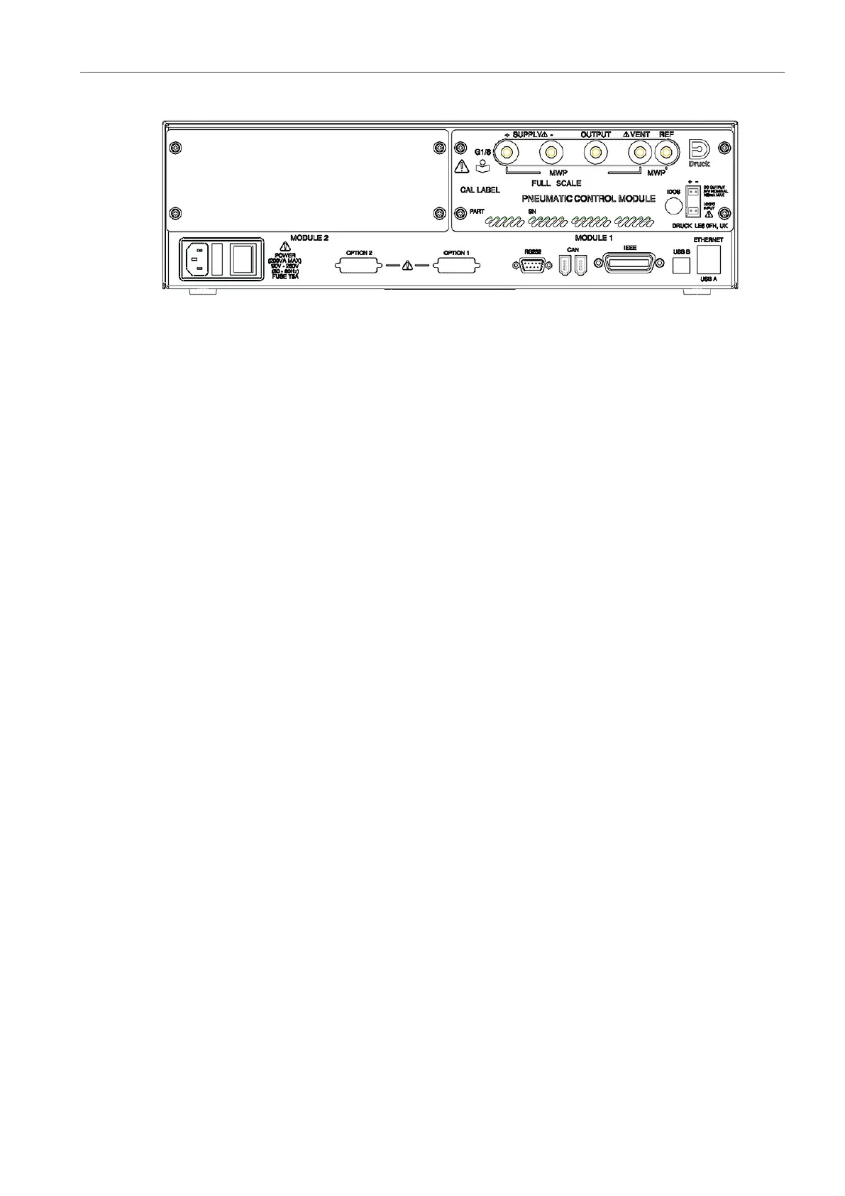
Figure 2-4: Control Module Rear View
When using two pressure control modules:
• The control module with the highest pressure rating is fitted to the right hand side. This is
labeled as Module 1 as viewed from the rear of the product. Refer to
Figure 2-4.
• If two control modules have the same pressure rating, the control module with the higher
serial number is fitted to the right hand side. This is labeled as Module 1 as viewed from the
rear of the product. Refer to
Figure
2-4.
All pneumatic connections must comply with the Pressure Equipment Directive (PED) or
equivalent regional pressure standard.
When connecting the output ports of two pressure control modules together make sure both are
either:
• ≤ 70 bar (1000 psi)
OR
• between 100 to 210 bar (1450 to 3000 psi).
To prevent over-pressurization of pneumatic parts and maintain compliance with the PED, do not
connect the output of modules with range of 70
bar (1000 psi) and below to modules with range
above 70
bar (1000 psi), e.g. 100 bar (1450 psi) and 210 bar (3000 psi) modules.
2.7 Supply Equipment
Pneumatic supplies should have isolation valves and, where necessary, conditioning equipment.
The positive pressure supply should be regulated to between 110% of the full-scale pressure
range and MWP stated on the control module.
To protect the instrument from over-pressure a suitable protection device (such as a relief valve
or bursting disc) must be fitted to prevent over pressurization.
On instruments without a negative supply, the positive pressure discharges from the system to
atmosphere through the negative supply port. Pipe the negative port to a safe discharge area, or
fit a diffuser to the negative port.
During system pressure vent operations, the pressure discharges from the system to atmosphere
through the negative and vent ports. Pipe both ports to a safe discharge area or fit a diffuser to
the negative port.