Copyright 2008 Baker Hughes Company.
10 | PACE5000/6000 Instruction Manual–English
Chapter 2. Installation
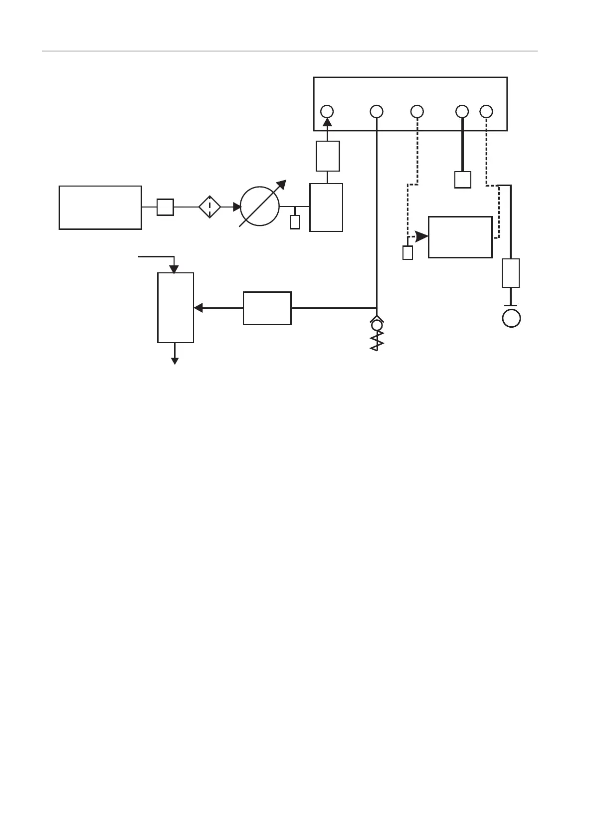
2.7.1.3 Pneumatic Connections with Negative Gauge Pressure Generator
Figure 2-7: Pneumatic Connections with Negative Gauge Pressure Generator
Note: Section 6, “Reference,” on page 43 for details of other system components.
2.8 Rack-mount Option
There must be enough space at the rear of the instrument for all the cables and pipes (tubes).
The length of the cables and pipes (tubes) must allow for the removal and installation of the
1 Pressure source 2 Conditioner
3 Filter 4 Regulate to between 110% full-scale and
MWP
5 Diffuser * 6 Unit under test
7 Optional reservoir † 8 Protection device
9 Optional differential connection 10 Vacuum generator ‡
11 Source pressure (regulated compressed air
supply)
12 Exhaust to atmosphere
13 Check valve ** 14 Manual external vent valves
a Atmosphere