Copyright 2008 Baker Hughes Company.
14 | PACE5000/6000 Instruction Manual–English
Chapter 2. Installation
The pin connections for the 9-pin D-type, RS-232 connector and the relationship between the
instrument and the RS-232 control signals, together with device interconnection interface is
shown in
Table
2-3. The instrument is configured as Data Circuit Terminating Equipment (DCE).
Note: For software handshaking use: TXD, RXD and GND. For hardware handshaking use: TXD,
RXD, GND, CTS, RTS and DTR.
2.10.2 IEEE 488 Interface
The interface complies with IEEE 488 standard.
The IEEE 488 parallel interface connects a computer/controller to one or more PACE1000
instruments and other instruments.
Up to 30 instruments can be connected through a high-speed data bus to the computer/controller.
Note: The length of each IEEE 488 cable must be less than 3 metres to comply with the EMC
requirements. Refer to Data Sheet.
2.10.2.1 Single Unit Installation
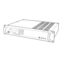
1. Connect an IEEE 488 connector/cable assembly to the rear panel of the instrument.
2. Connect the other end of the connector/cable assembly to the IEEE 488 connector on the
controller/computer.
3. Change the IEEE 488 communication parameters. Refer to Section 6.9.4.2, “IEEE 488,” on
page 50.
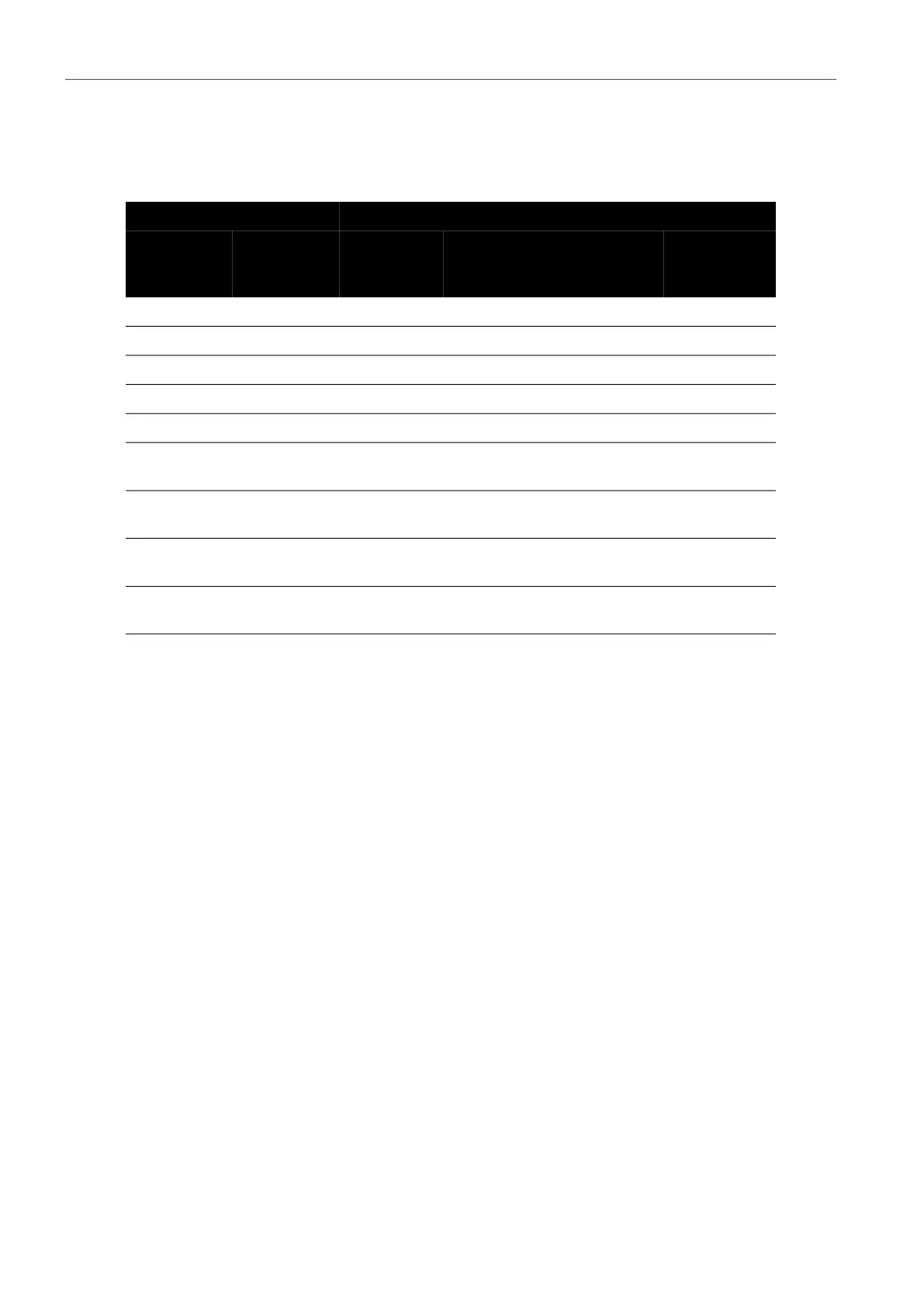
Table 2-3: RS-232 Connections
Instrument Control Line Computer
Instrument
Function
9-way
D-type
Pin No.
Signal
Direction
RS-232
Terminology
9-way
D-type
Pin No.
25-way
D-type
Pin No.
RxD (I/P) 3 TxD 3 2
TxD (O/P) 2 RxD 2 3
GND 5 GND 5 7
CTS (I/P) 7 RTS 7 4
RTS (O/P) 8 CTS 8 5
Pulled high
internally
1
RLSD
(DCD)
1 8
Not
connected
4 DTR 4 20
Pulled high
internally
6
DSR
DCE Ready
6 6
Equipment
chassis
Connector
shell
Cable Screen - 1