Copyright 2008 Baker Hughes Company.
12 | PACE5000/6000 Instruction Manual–English
Chapter 2. Installation
2.9 Power Connection
1. Install an accessible power isolator to use as the disconnecting device in the power supply
circuit.
2. For power supply range, power rating and installation category, refer to “General
Specification” on page iii.
Note: The power must be protected by a fused or overload-protection device.
3. Connect the power supply to the instrument.
4. Switch the power supply on.
5. Check that the front panel display shows the power-up sequence. Refer to Section 3.2,
“Power-up Sequence,” on page 17.
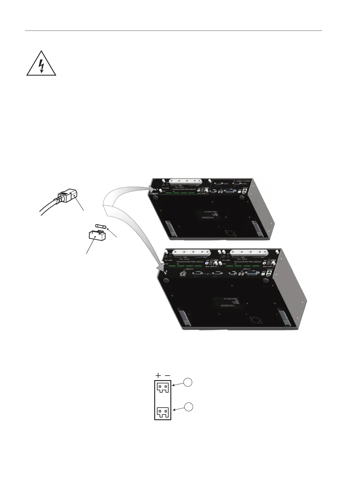
Figure 2-9: Electrical Connections
2.9.1 Pressure Control Module DC Power and Logic Input Connectors
The DC power output is rated at 24 V DC, 100 mA. An internal self-resetting fuse protects the
output.
RISK OF ELECTRIC SHOCK The ground lead of the instrument must be
connected to the AC supply protective safety ground.
Isolate the power supply before making any electrical connections to the rear
panel.
1 IEC connector 2 Fuse carrier
3 Fuse
1 DC power output 2 Logic (Switch) input