Copyright 2008 Baker Hughes Company.
38 | PACE5000/6000 Instruction Manual–English
Chapter 4. Maintenance
b. De-pressurize all pressure supply inlet and output lines.
c. Partially or completely withdraw the instrument.
3. Isolate the power supply to the instrument and disconnect the IEC power supply connector
(1).
4. Remove the fuse carrier (2) from the power supply input socket assembly.
5. Remove the fuse cartridge (3).
4.6.1.2 Replace Fuse
Refer to Figure 4-1.
1. Check for the correct type of fuse. Refer to Table
4-2.
2. Replace the fuse.
3. Refit the fuse carrier (2) in the power supply inlet socket assembly.
4. Refit and reconnect rack-mounted units. Refer to Section 2, “Installation,” on page 3.
5. Switch on the power supply and set the power supply switch to ON.
6. If the fuse blows immediately with power-on, contact the manufacturer or Service Agent.
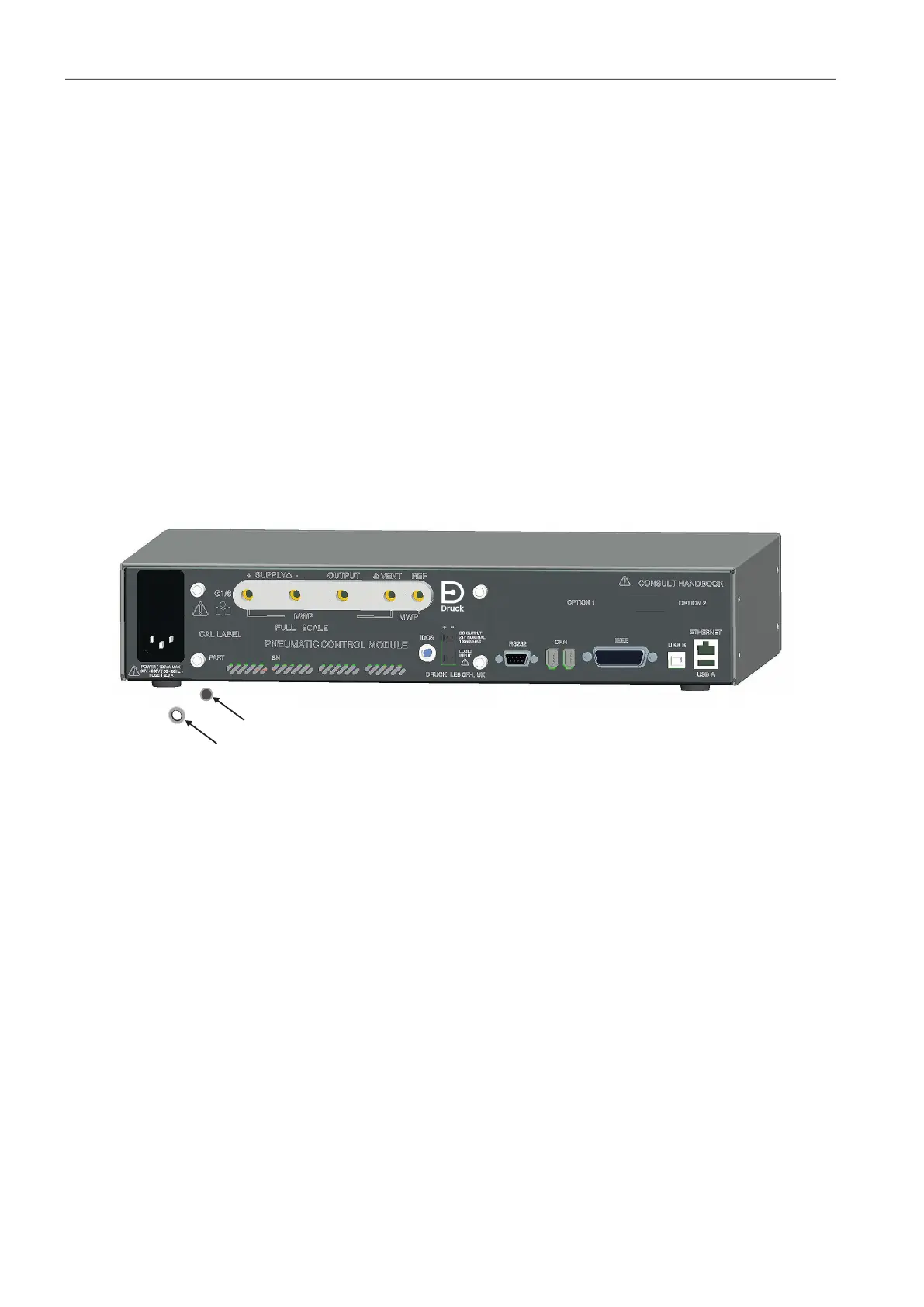
4.6.2 Pressure Control Module Filters
Figure 4-2: Pressure Control Module Filter Replacement
4.6.2.1 Remove Filter
Refer to Figure 4-2.
1. Set the power switch to OFF. If the PACE is not rack-mounted, got to step 3.
2. For access to rack-mounted instruments, the following actions maybe required:
a. Isolate pneumatic supplies.
b. De-pressurize all pressure supply inlet and output lines.
c. Partially or completely withdraw the instrument.
3. Isolate the power supply to the instrument and disconnect the IEC power supply connector.
4. Disconnect the pneumatic pipes (tubes) from the pressure control module.
5. Release the four cross-head screws (drive size 2) securing the pressure control module in
the instrument case.
6. Remove the pressure control module to access to the filters.
7. Use a 5 mm hexagonal key, to release the filter retainer (1).
8. Remove the five filters (2). If necessary, invert the pressure control module to aid removal.
1
Retainer
2 Filter