Copyright 2008 Baker Hughes Company.
English–PACE5000/6000 Instruction Manual | 39
Replacement Parts
4.6.2.2 Replace Filter
Refer to Figure 4-2.
1. Insert five new filter into each of the pressure connections.
2. Use a 5 mm hexagonal key, to secure each filter retainer. Do not over tighten.
3. Refer to Section 2, “Installation,” on page 3.
4.6.3 Pressure Control Module Replacement
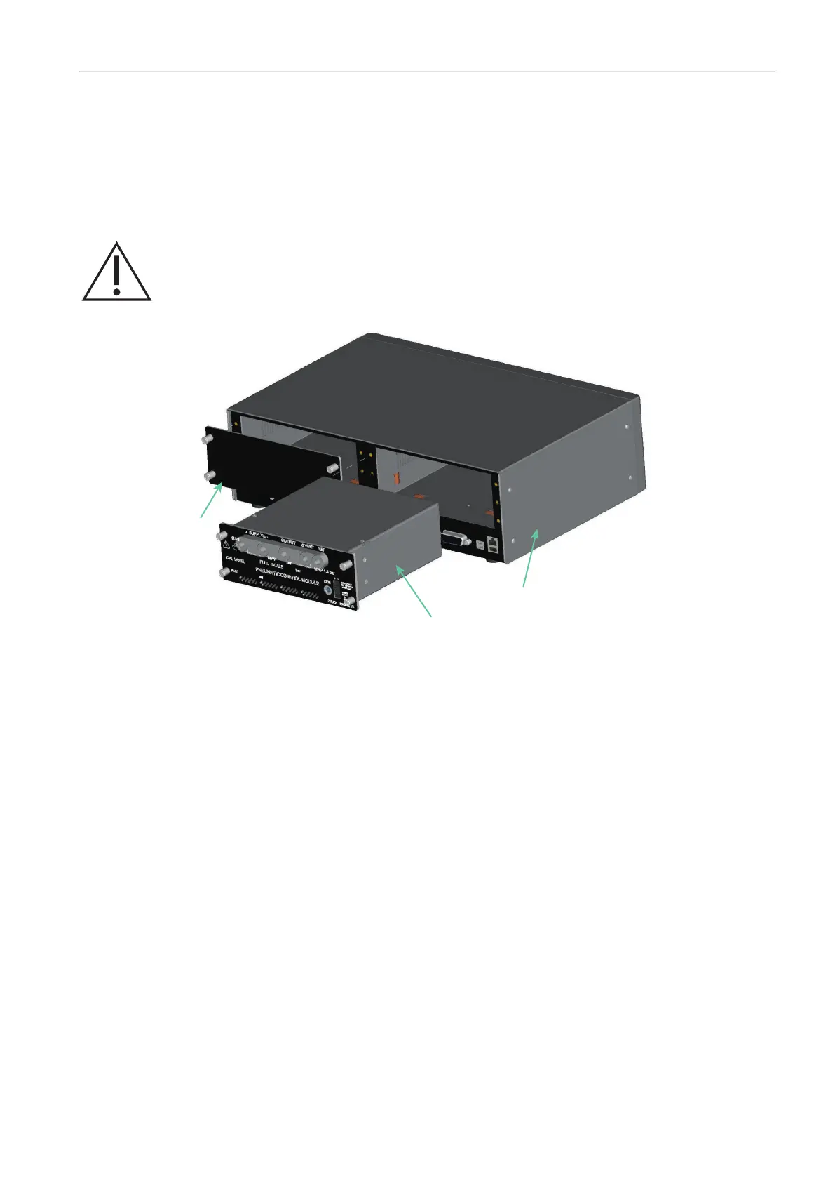
Figure 4-3: Pressure Control Module Replacement
4.6.3.1 Remove Pressure Control Module
Refer to Figure 4-3 and Section 2, “Installation,” on page 3.
1. Release the four cross-head screws (drive size 2) securing the pressure control module in
the instrument case.
2. Remove the pressure control module from the chassis.
3. Fit the blanking plate (3) (supplied) to protect the internal components.
4.6.3.2 Replace Pressure Control Module
Refer to Figure 4-3 and Section 2, “Installation,” on page 3.
1. Fit a fully compatible pressure control module (1) into the instrument case (2).
2. Secure the four cross-head screws (drive size 2) securing the pressure control module in
the instrument case.
WARNING Turn off the source pressure and vent the pressure lines before
disconnecting or connecting the pressure lines. Proceed with care.
1 Pressure Control Module 2 Instrument case
3 Blanking plate