Copyright 2008 Baker Hughes Company.
English–PACE5000/6000 Instruction Manual | 13
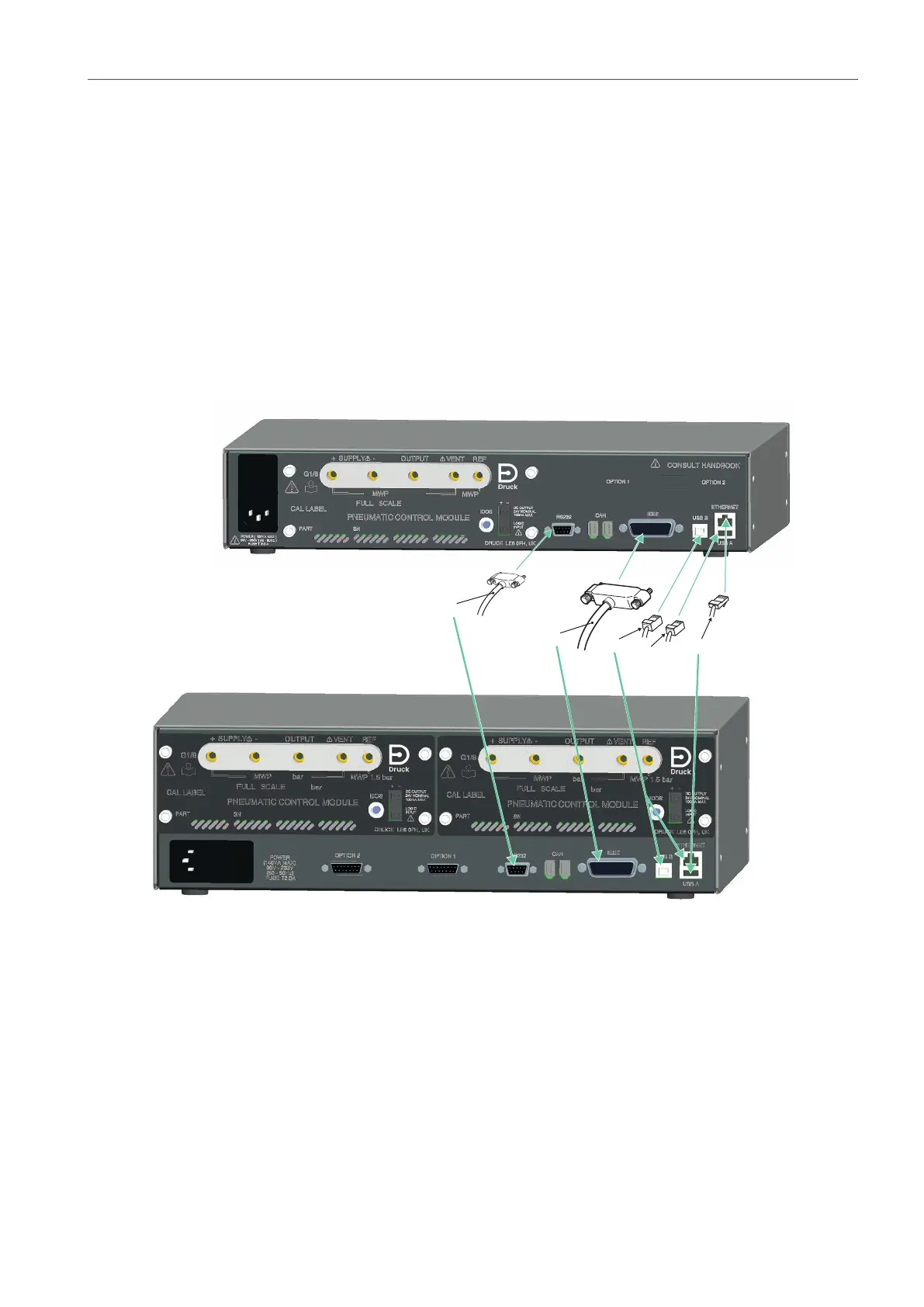
Communication Connection
This Logic (Switch) input can be used to trigger the instrument from a pressure switch contact
during the Pressure Switch Task. Refer to
Section 3.4, “Control Mode,” on page 21.
Connections are not polarized and can be connected either way. An internal opto-isolator
protects the input.
The Logic (Switch) input can be energized by external SELV compliant equipment.
2.10 Communication Connection
Connect the applicable connectors into the rear panel communications ports. If appropriate,
secure with the captive screws.
Note: The RS-232 and IEEE 488 interfaces are both enabled at power-up. Set the required
parameters in Supervisor Setup/communications menu. Refer to
Section 3.8, “Supervisor
Setup,” on page
31.
Note: Refer to the Data Sheet for a list of optional communication ports.
Figure 2-10: Communication Connectors
2.10.1 RS-232 Interface
When using the RS-232 interface, a cable must be connected directly from the instrument to a
suitable port on the computer in a ‘point to point’ link.
1 RS232 3 IEEE488 4 USB B
5 USB A 6 Ethernet