Copyright 2008 Baker Hughes Company.
8 | PACE5000/6000 Instruction Manual–English
Chapter 2. Installation
2.7.1 Pneumatic Connection Examples
The following notes apply to the connection examples:
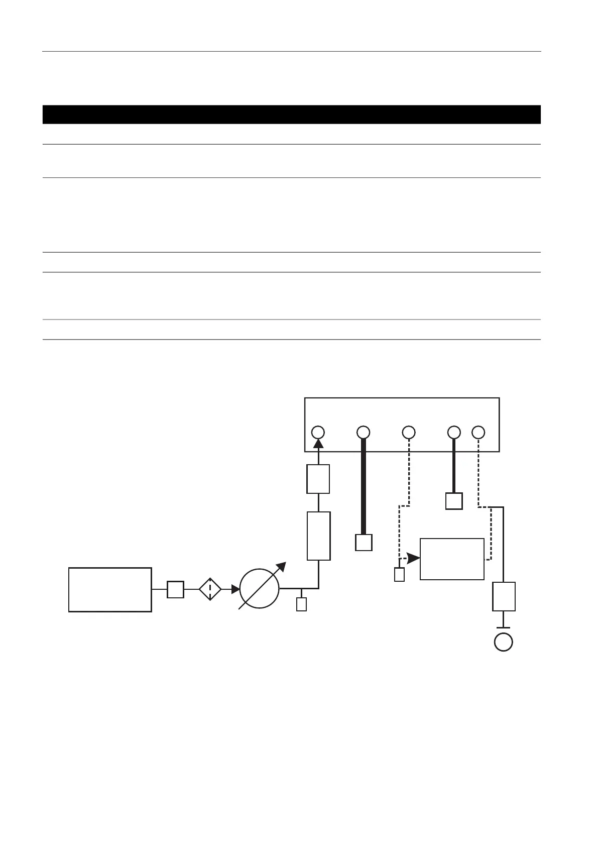
2.7.1.1 Pneumatic Connections without Vacuum Supply
The examples below show a single channel connection detail, using supply equipment described
above.
Figure 2-5: Pneumatic Connections without Vacuum Supply
Note: Refer to Section 6, “Reference,” on page 43 for details of other system components.
Note Description
*
High pressure gas exhaust - depending on pressure range.
**
Optional vacuum system kit, allows the -ve port gas to be directly discharged to
atmosphere, by-passing the vacuum pump.
†
Optimum controller transient response and minimum time to set-point may be
degraded if either the pneumatic supply or vacuum system has restricted flow.
Installing a reservoir volume, which has a larger capacity than the load volume,
located in close proximity to the controller supply ports can improve the controller
response.
‡
Optional negative gauge pressure generator kit.
For ranges of 70 bar (1000 psi) and above, fit a suitable protection device to prevent
overpressure. For example, fit a relief valve or bursting disc. The protection device
must limit the applied pressure to below the MWP.
Optional differential connection kit.
1 Pressure source 2 Conditioner
3 Filter 4 Regulate to between 110% full-scale and
MWP
5 Diffuser * 6 Unit under test
7 Optional reservoir † 8 Protection device
9 Optional differential connection 14 Manual external vent valves
a Atmosphere