Connector Pinouts and LEDs
▲
■■■■■■■■■■■■■■■■■■■■■■■■■■■■■■■■■■■■■■■■■■■■■■■■■■■■■■■■■■■■■■■■■■■■■■■■■■■■■■■■■■■■■■■■■
DS1103 Hardware Installation and Configuration March 2004
I■■■■■■■■■■■■■
▼
174
■■■■■■■■■■■■■■■▼
N
The CAN bus lines (CANH, CANL) are not terminated with a resistor on
the DS1103.
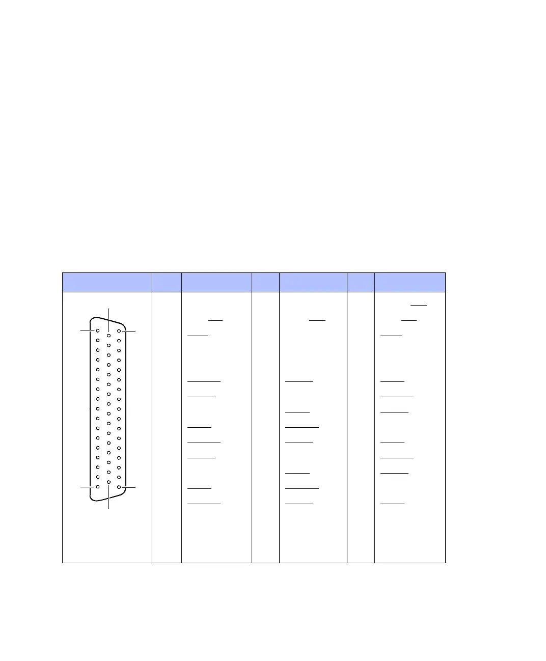
Pinout of
Sub-D connectors
Because the pin numbering used for Sub-D connectors is not
standardized, the following illustrations show the numbering used
(viewed from the top of a female connector).
C
Do not rely on the numbers written on Sub-D connectors.
The table below shows the pin assignment of the Sub-D connector
P3A. Signal names in parentheses apply when the UART is set to the
RS422 mode.
Connector P3A Pin Signal Pin Signal Pin Signal
1 GND 34 Not used for
RS232 (TXD
)
2 DTR (RTS
) 18 DCD (RXD) 35 DSR (CTS)
3STXD
19 GND 36 SRXD
4– 20– 37–
5– 21– 38GND
6PHI90(7)
22 PHI0(7) 39 IDX(7)
7 PHI0(6) 23 GND 40 PHI90(6)
8GND 24IDX(6) 41 PHI0(1)
9IDX(1) 25 PHI90(1) 42 GND
10 PHI90(2)
26 PHI0(2) 43 IDX(2)
11 PHI0(3) 27 GND 44 PHI90(3)
12 GND 28 IDX(3) 45 PHI0(4)
13 IDX(4) 29 PHI90(4) 46 GND
14 PHI90(5)
30 PHI0(5) 47 IDX(5)
15 GND 31 GND 48 GND
16 VCC2 (+ 5 V) 32 GND 49 VCC2 (+ 5 V)
17 VCC3 (+ 5 V) 33 VCC3 (+ 5 V) 50 GND
1
34
18
50
33
17
 Loading...
