■■■■■■■■■■■■■■■■■■■■■■■■■■■■■■■■■■■■■■■■■■■■■■■■■■■■■■■■■■■■■■■■■■■■■■■■■■■■■■■■■■■■■■■■■■■■■■■■
▼
Installing the Hardware
DS1103 Hardware Installation and Configuration March 2004
41
▲
■■■■■■■■■■I
▲■■■■■■■■■■■■■■■
C
CAUTION! Improper handling will damage the fan of the board.
■ Do not touch any components of the fan, neither during operation
nor when it has stopped.
■ Do not apply pressure to the fan bearing during installation and
removal of the board.
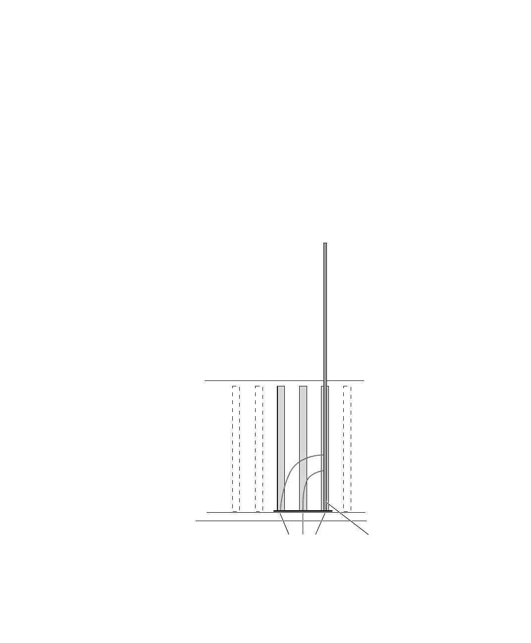
5 Insert the DS1103 and screw on the board’s triple connector.
The connector next to the board is labeled P1, the second
connector is labeled P2 and the third one P3.
6 Close the enclosure.
DS1103Triple connector bracket: P3, P2, P1
 Loading...
