Machine description - Electrical system
ICA134-3EN2.pdf2012-04-13
Machine description - Electrical system
Fuses
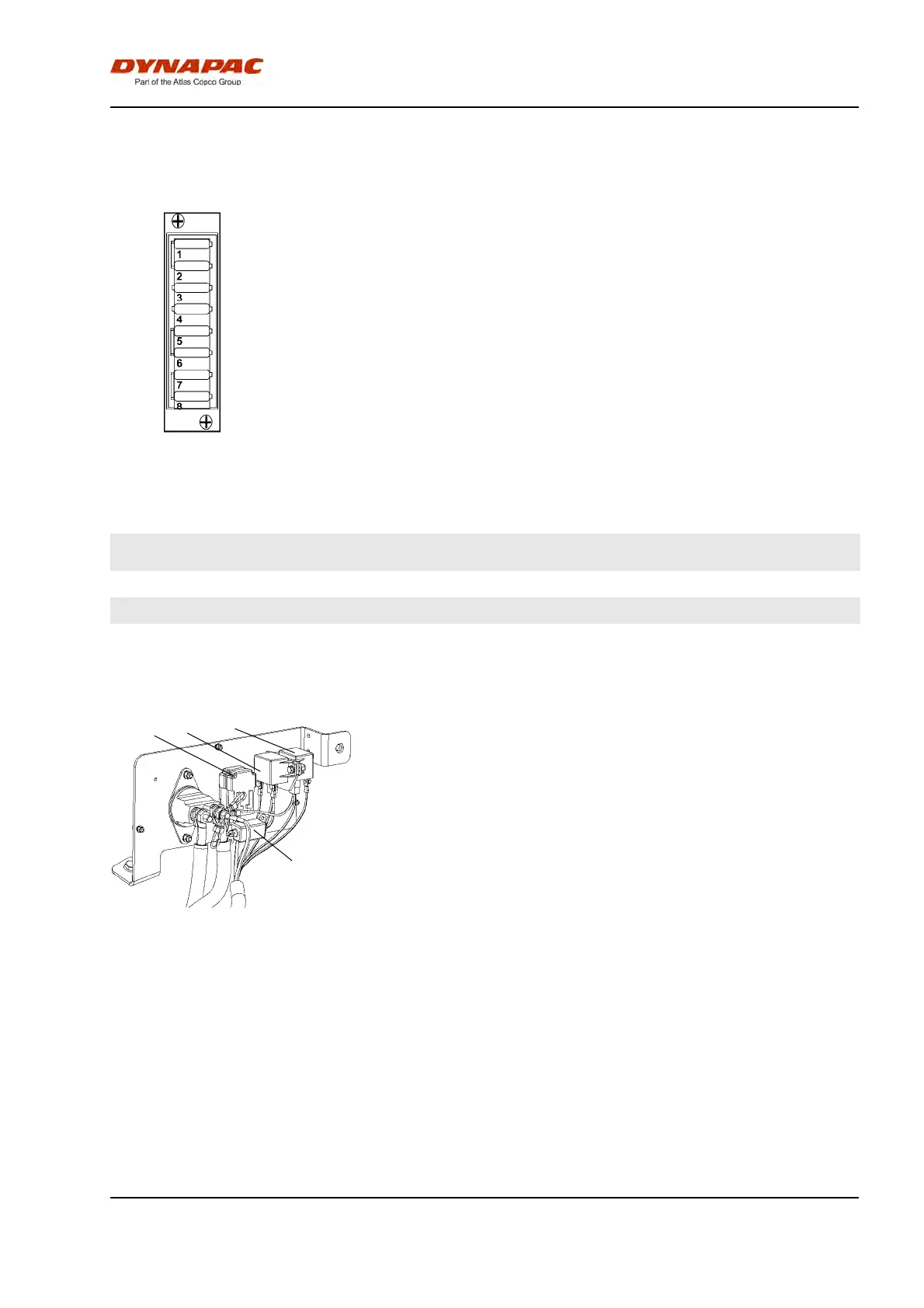
Fig. Fuse box
The figure shows the position of the fuses.
The table below gives fuse amperage and function. All
fuses are flat pin fuses.
The machine is equipped with a 12V electrical system
and an AC alternator.
Fuses in the fuseboxFuses in the fusebox
1.
Emergency stop, ECU, reversing alarm,
neutral position, seat switch, vibration
15A
5.
Driving lights: headlights, position lights,
brake lights, number plate lights
20A
1.
Emergency stop, ECU, reversing alarm,
neutral position, seat switch, vibration
15A
5.
Driving lights: headlights, position lights,
brake lights, number plate lights
20A
2.
Horn, buzzer, control panel 10A
6.
Direction indicators, hazard flashers 10A
2.
Horn, buzzer, control panel 10A
6.
Direction indicators, hazard flashers 10A
3.
Hazard beacon, strike-off blade 10A
7.
Right direction indicators, side blinkers 5A
3.
Hazard beacon, strike-off blade 10A
7.
Right direction indicators, side blinkers 5A
4.
Working lights 20A
8.
Left direction indicators, side blinkers 5A
4.
Working lights 20A
8.
Left direction indicators, side blinkers 5A
Main fuses
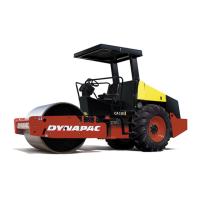
Fig. Engine compartment
1. Starter relay
2. Main fuse
3. Preheating relay
4. Fuse for preheating relay
4
3
1
2
There is one main fuse (2). It is located behind the
battery master switch. The three screws need to be
unscrewed to remove the plastic cover.
The fuse if of the flat pin type.
The starter relay (1), preheating relay (3) and fuse for
the preheating relay (4) are also fitted here.
Supply standard 40A (Orange)Supply standard 40A (Orange)
Supply lighting * 20A (Yellow)Supply lighting * 20A (Yellow)
Power supply, preheater 100A (Blue)Power supply, preheater 100A (Blue)
* Optional equipment * Optional equipment
37