Digital Keypad Operation
2-4 MVX9000 User Manual
Overview of the
MVX9000 Drive
Digital Keypad Operation
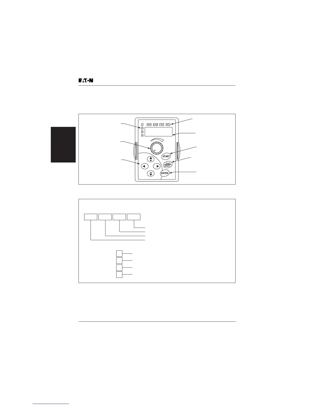
The digital keypad includes the display panel and the keypad. The display panel
provides the parameter display and shows the operation status of the AC drive.
The keypad provides programming and control interface.
Figure 2-3: Description of Digital Keypad
Figure 2-4: Explanation of the LED Indicators
Up, Down and
Right/Left Keys
Scrolls Display,
Enter/Exit Parameter Mode,
Change Parameter Settings
Potentiometer
For Setting
Input Speed Command
LED Indicators
Lamp Lights to Indicated
Frequency Input, Hz Output,
Amps and User Defined Units
STOP/RESET Key
Stop Command and Reset
the Drive After a Fault Occurs
LED Display
Indicates Motor and
Drive Parameter
LED Indicators
Lamp Lights During Run,
Stop, Fwd, Rev Operations
ENTER Key
Used in Parameter Mode
to Enter and Change Values
START Key
Start Command
LED Displays
Green lamp lights during REV operation.
Green lamp lights during FWD operation.
Red lamp lights by pressing STOP.
Green lamp lights by pressing RUN.
Lamp lights to indicate input frequency reference
Lamp lights to indicate output Hz
Lamp lights to indicate output amps
Lamp lights to indicate user defined units
RUN STOP FWD REV
F
H
A
U

 Loading...


