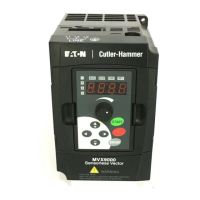
MVX9000 Parameter Listing
B-6 MVX9000 User Manual
Parameter Tables
Table B-4: 50 — DRIVE CONTROL
Modbus Groups Page # Description Range Default
User
Settings
0300H 50.01 5-31 Source of Master
Frequency
00: Master Frequency
determined by digital keypad
up/down
01
01: Master Frequency
determined by keypad
potentiometer
02: Master Frequency
determined by 0 to +10V
input on AI1 terminal
03: Master Frequency
determined by 4 – 20 mA
input on AI2 terminal
04: Master Frequency
determined by RS-485
communication interface
0301H 50.02 5-31 Source of Operation
Command
00: Operation command
determined by digital keypad
00
01: Operation command
determined by external
control terminals, keypad
STOP is effective
02: Operation command
determined by external
control terminals, keypad
STOP is ineffective
03: Operation command
determined by RS-485
interface, keypad STOP is
effective
04: Operation command
determined by RS-485
interface, keypad STOP is
ineffective
0302H 50.03 5-31 Stop Methods 00: Ramp to Stop 00
01: Coast to Stop
0303H 50.04 5-32 Maximum Output
Frequency
50.0 to 400.0 Hz 60.0
0304H 50.05 5-32 Motor Nameplate
Frequency
10.0 to 400.0 Hz 60.0
0305H 50.06 5-32 Motor Nameplate
Voltage
115/230V 0.1 to 255.0V 230.0
460V 0.1 to 510.0V 460.0
575V 0.1 to 637.0V 575.0
0306H 50.07 5-32 Mid-point Frequency 0.1 to 400.0 Hz 1.5
0307H 50.08 5-33 Mid-point Voltage 115/230V 0.1 to 255.0V 10.0
460V 0.1 to 510.0V 20.0
575V 0.1 to 637.0V 26.1
0308H 50.09 5-33 Minimum Output
Freq
0.1 to 20.0 Hz 1.5
0309H 50.10 5-33 Minimum Output
Voltage
115/230V 0.1 to 50.0V 10.0
460V 0.1 to 100.0V 20.0
575V 0.1 to 637.0V 26.1
030AH 50.11 5-34 Sensorless Vector
Enable
00: Disable 00
01: Enable

 Loading...