Step-by-Step Installation
MVX9000 User Manual 4-3
Start-Up
Procedures
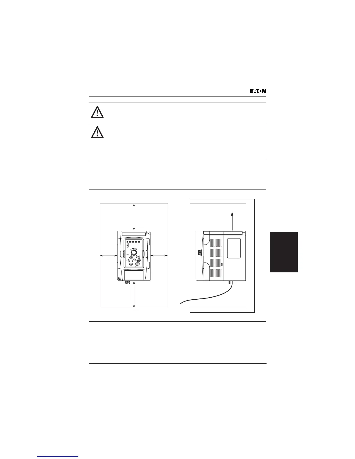
Step 2: The installation should be made on a solid, non-flammable, vertical
surface that is a relatively clean and dry environment. In order to ensure enough
room for air circulation around the inverter to aid in cooling, maintain the
specified clearance around the inverter specified in Figure 4-1.
Figure 4-1: Clearances and Air Flow in Inches (mm)
CAUTION!
Be sure not to install or operate an inverter which is damaged or has
missing parts. Otherwise, it may cause injury to personnel.
CAUTION!
Be sure to install the inverter in a well-ventilated room which does not
have direct exposure to sunlight, a tendency for high temperature,
high humidity or dew condensation, high levels of dust, corrosive gas,
explosive gas, inflammable gas, grinding-fluid mist, salt damage, etc.
Otherwise, there is the danger of fire.
3.0 (76)
or More
1.0 (25)
or More
1.0 (25)
or More
Air Flow
3.0 (76)
or More

 Loading...


