Group 40 — Outputs
5-28 MVX9000 User Manual
Descriptions of
Parameter Settings
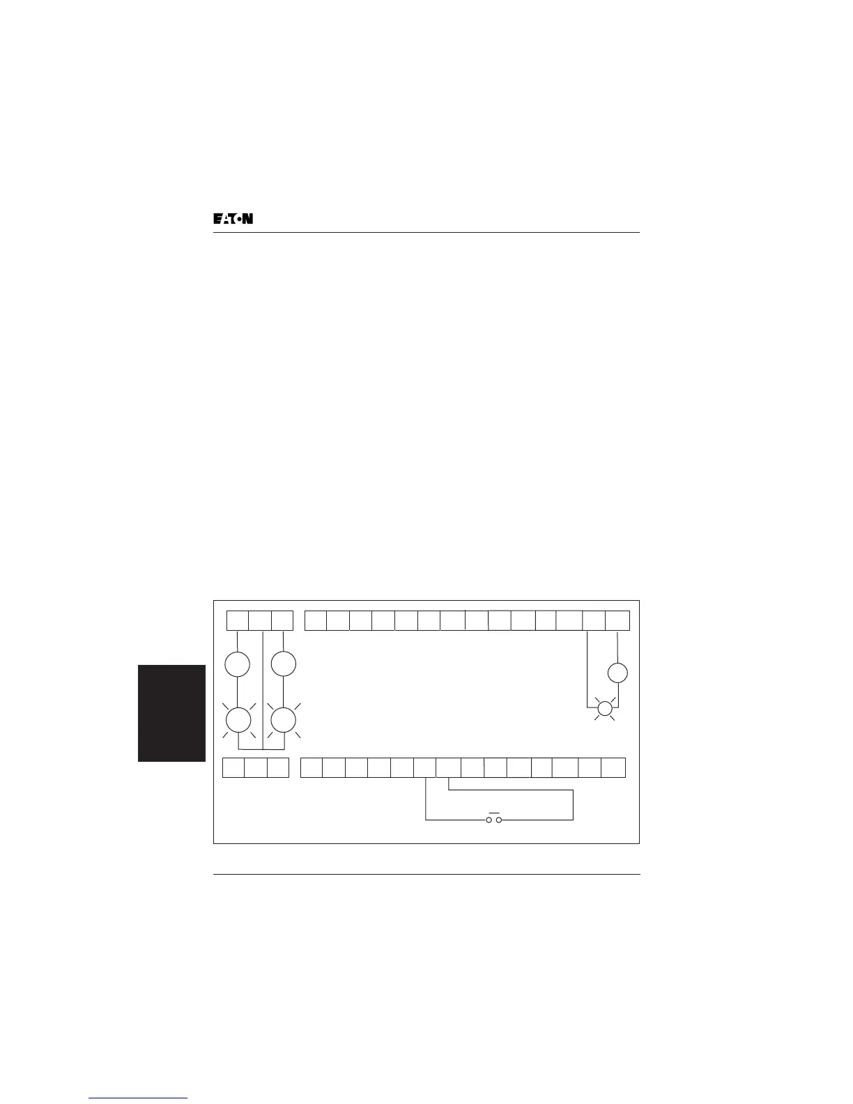
Figure 5-33: R01, R02 and R03 Settings
40.04
Relay Output
Terminal RO1, RO2,
RO3
Range: 00 to 20 Default: 03
00 Not Used
01 Ready
02 Inverter output is active
03 Inverter Fault
04 Warning (See warning codes in Chapter 7)
05 At speed
06 Zero Speed
07 Above desired frequency (40.05)
08 Below desired frequency (40.05)
09 PID supervision
10 Over voltage supervision
11 Over heat supervision
12 Over current stall supervision
13 Over voltage stall supervision
14 Low voltage indication
15 PLC program running
16 PLC program step complete
17 PLC program completion
18 PLC program pause
19 Terminal count value attained
20 Preliminary count value attained
21 Reverse direction notification
22 Under current detection
23 Inverter RUN command state
AC
AC
LT
LT
DC
LT
–
+
25:Counter reset
RO3 RO2 RO1
DI1 DI2
DI3
DI4
DI5
DI6
COM
AO+
AI1
+10V
AI2
DO1
DOC
COM
RO3 RO2 RO1
DI1 DI2
DI3
DI4
DI5
DI6
COM
AO+
AI1
+10V
AI2
DO1
DOC
COM

 Loading...


