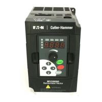
MVX9000 Parameter Listing
MVX9000 User Manual B-3
Parameter Tables
Table B-2: 30 — INPUTS
Modbus Groups Page # Description Range Default
User
Settings
0100H 30.01 5-7 Minimum reference
value (0 – 10V)
0.0 to 10.0V 0.0
0101H 30.02 5-7 Maximum reference
value (0 – 10V)
0.0 to 10.0V 10.0
0102H 30.03 5-7 Invert reference
signal (0 – 10V)
00: Not inverted 00
01: Inverted
0103H 30.04 5-7 Minimum reference
value (4 – 20 mA)
0.0 to 20.0 mA 4.0
0104H 30.05 5-7 Maximum reference
value (4 – 20 mA)
0.0 to 20.0 mA 20.0
0105H 30.06 5-7 Invert reference
signal (4 – 20 mA)
00: Not inverted 00
01: Inverted
0106H 30.07 5-7 Potentiometer Offset 0.0 to 100.0% 0.0
0107H 30.08 5-8 Potentiometer Bias
Polarity
00: Positive, 01: Negative 00
0108H 30.09 5-8 Potentiometer Slope 0.1 to 300.0% 100.0
0109H 30.10 5-8 Potentiometer
Direction
00: Forward Motion Only 00
01: Reverse Motion Enable
010AH 30.11 5-14 Digital Input Terminal
(DI1, DI2)
01: DI1-FWD / STOP, DI2-REV /
STOP
02
02: DI1-RUN / STOP, DI2-REV /
FWD
03: DI1 - RUN momentary
(NO), DI2 - REV / FWD, DI3 -
STOP momentary (NC)
010BH
010CH
010DH
010EH
30.12
30.13
30.14
30.15
5-15
5-15
5-16
5-16
Digital Input Terminal
(DI3)
Digital Input Terminal
(DI4)
Digital Input Terminal
(DI5)
Digital Input Terminal
(DI6)
00: Not used 05
06
07
03
01: External Fault (NO)
02: External Fault (NC)
03: External Reset (NO)
04: External Reset (NC)
05: Multi-Speed 1
06: Multi-Speed 2
07: Multi-Speed 3
08: Jog
09: Second Acceleration/
Deceleration Time
10: Control Place: I/O
Terminal
11: Control Place: Keypad
12: Control Place:
Communication
13: Increase Speed during
RUN command
14: Decrease Speed during
RUN command
15: Forward/Reverse
16: Parameter Lock

 Loading...