107
support@edgeovens.com
Technical Support: +1 (724) 628 3050
OPERATION
FIGURE 3-65 FIGURE 3-66
FIGURE 3-67
PREVENTATIVE MAINTENANCE
BURNER ASSEMBLY CLEANING (CONTINUED)
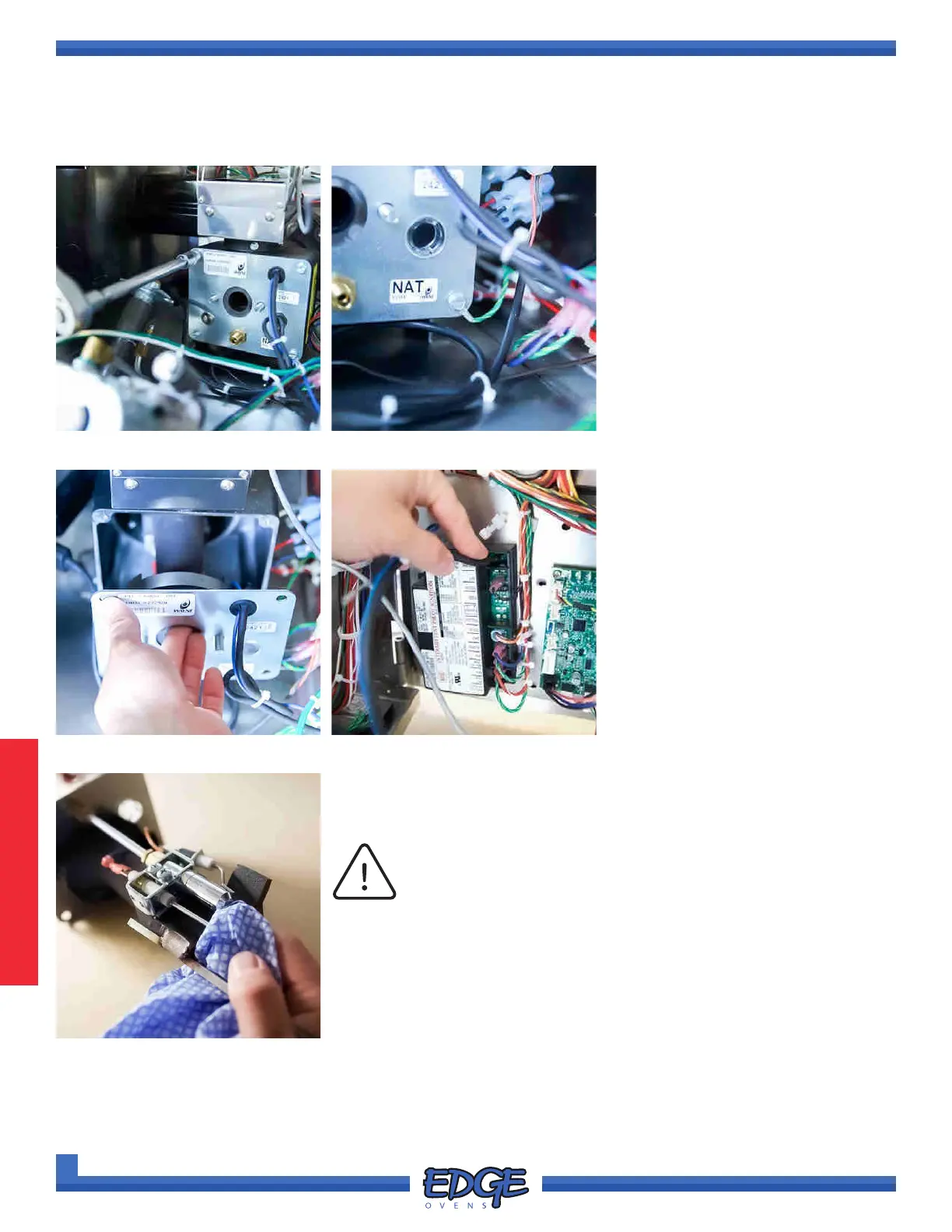
8. Using a 5/16” socket with long
extension and ratchet, remove
the four (4) machine screws in
each corner of the burner face
plate (Figure 3-65).
Please note the position of
ground wire secured to the
burner assembly face plate, on
reassembly this must be installed
correctly (Figure 3-66).
9. Insert your nger into the venturi
opening and carefully pull the
burner assembly from the burner
tube (Figure 3-67).
10. To disconnect the burner
assembly from the ignition
module, remove the spade
connector from the SPARK
terminal (Figure 3-68).
FIGURE 3-68
FIGURE 3-69
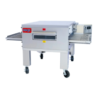
11. Using a moist cloth, wipe the white/gray material from the SPARK
ELECTRODES and PILOT BURNER. Use scuff pad or emery cloth to
scuff off the remaining material (Figure 3-69).
The ignition spark originates from the electrode and arcs to
the pilot burner. It is important to clean the entire pathway.
NOTICE
12. Scuff the ame rod, if you desire, this is backup ame recognition device
that can be plugged in should the optical ame detector fail.