109
support@edgeovens.com
Technical Support: +1 (724) 628 3050
OPERATION
PREVENTATIVE MAINTENANCE
BURNER ASSEMBLY CLEANING (CONTINUED)
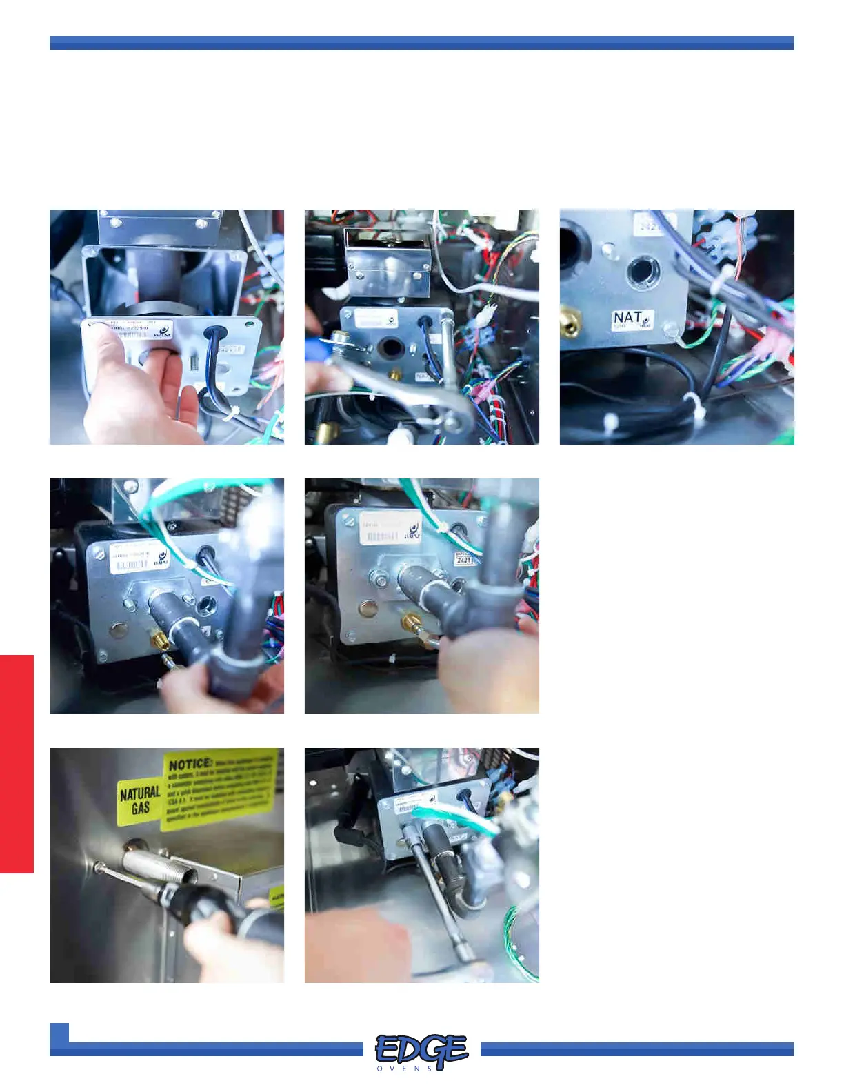
FIGURE 3-73 FIGURE 3-74FIGURE 3-72
13. Carefully install the venturi back within the burner housing (Figure 3-72) and install the 4 machine screws
(Figure 3-73), making sure to install the grounding wire on the lower right hand side position (Figure 3-74)
and reconnect the spade connector to the SPARK terminal on the ignition module
FIGURE 3-75
14. Install the gas train on the
burner face plate (Figure 3-75),
connect the pilot tube and start
the 1/2” nuts on both (Figure
3-76), DO NOT TIGHTEN them
yet.
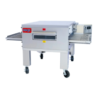
FIGURE 3-76
FIGURE 3-77
15. Install the two (2) screws to
secure the inlet piping to the
control cabinet. (Figure 3-77)
16. Tighten the 1/2” nut on the pilot
tube and the two (2) 1/2” nuts on
the burner face plate to secure
the gas train. (Figure 3-78)
FIGURE 3-78