55
support@edgeovens.com
Technical Support: +1 (724) 628 3050
INSTALLATION
FIRE SUPPRESSION
FIGURE 2-130
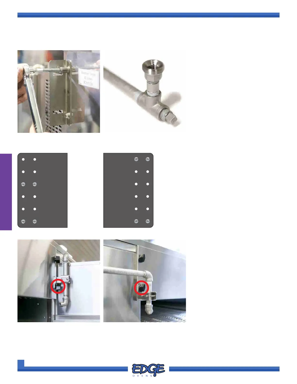
3. Begin with the LOWEST oven
(BOTTOM DECK), install
BRACKET A
1
and A
2
(Figure
2-130), using the separated lower
sections of the pre-plumbed
pipework, this will be identiable
by the presence of the TEE
joint (Figure 2-131). Securing
fasteners should be left loose for
adjustment.
FIGURE 2-131
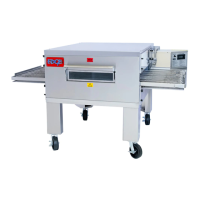
FIGURE 2-132
CABINET SIDE (A
1
& A
3
)
FIGURE 2-133
NON-CABINET SIDE (A
2
& A
4
)
1
2
3
4
5
6
1
2
3
4
5
6
FIGURE 2-134
4. Remove the LOWER, BACK
wingnuts from the UPPER END
PANEL from each end of the
oven. (Figure 2-134 & Figure
2-135).
Upper end panel wingnuts should
be removed from the side closest
to the oven rear.
FIGURE 2-135
It is important to ensure the
correct bracket is installed on the
correct oven side see Figure 2-132
& 2-133.
Please note, all shown images
have be provided without the
pipework in place for clarity
of install, it is NOT necessary
to remove the piping from the
brackets prior to install.
PIPE & BRACKET INSTALL (CONTINUED)