56
support@edgeovens.com Technical Support: +1 (724) 628 3050
INSTALLATION
FIRE SUPPRESSION
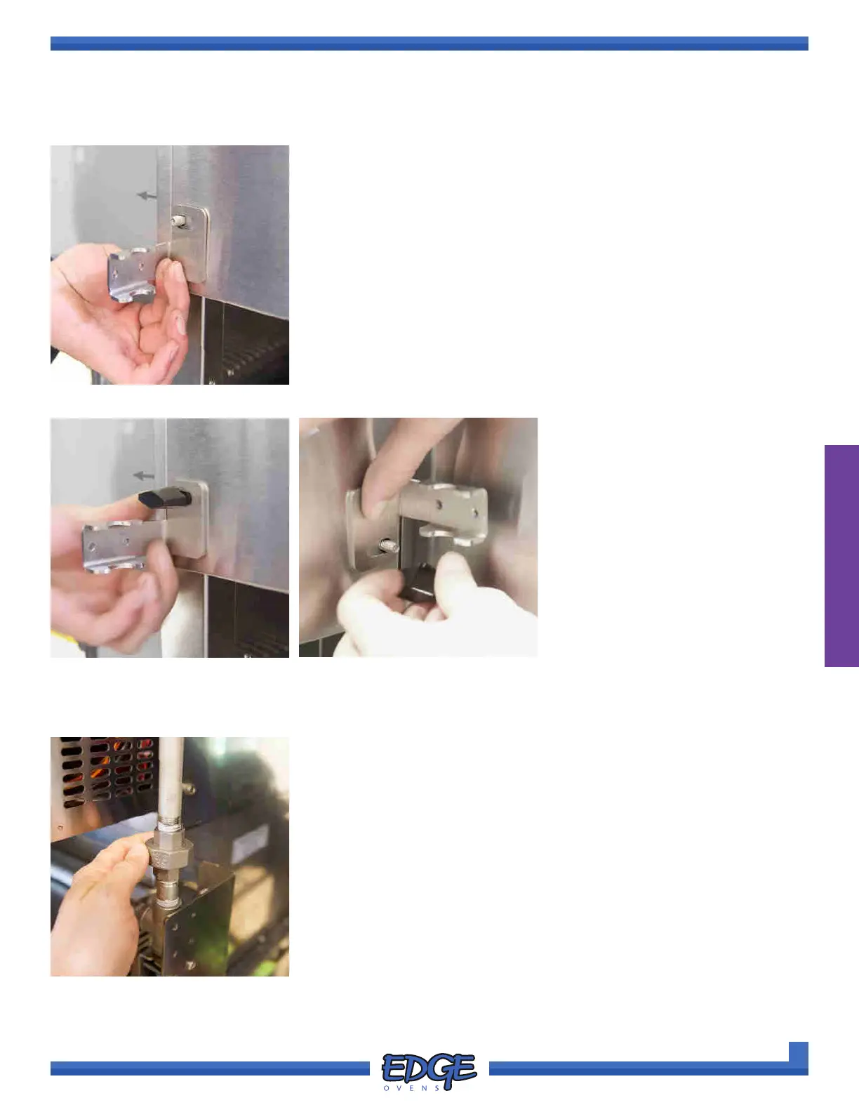
FIGURE 2-136
5. Continue by installing BRACKET B
1
and B
2
on the threaded studs,
securing with the previously removed wingnuts. (Figure 2-136).
Please note the orientation of the BRACKET, on the NON-CONTROL
CABINET side, the pipe clamp section of the bracket will sit below the
wingnut (Figure 2-137). On the CONTROL CABINET side it will be
rotated 180° where the pipe clamp will sit above the wingnut (Figure
2-138).
Please note, all shown images have be provided without the
pipework in place for clarity of install, it is not necessary to
remove the piping from the brackets prior to install.
FIGURE 2-138
FIGURE 2-137
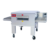
6. Once the BRACKET A
1
, A
2
, B
1
and B
2
have been installed and pipework is loosely secured repeat the
bracket and pipework installation for all subsequent oven decks.
FIGURE 2-139
7. Once pipework installation is complete, loosely join the unions
between each oven deck section on both sides of the oven. (Figure
2-139)
PIPE & BRACKET INSTALL (CONTINUED)