Resistance welder MULTISPOT MI-100control
Design and functionality
27
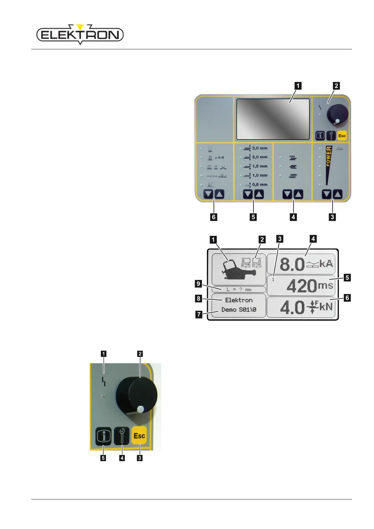
4.3 Display and control elements
4.3.1 On the display and control panel
1 Display
see also Fig. 13
2 Selection elements
see also Fig. 14
3 Touch key for power selection
4 Touch key for selecting welding jobs
(from top to bottom):
high strength steel (HSS)
3 layer sheets
galvanised sheets
5 Touch key for selecting sheet gauges
6 Touch key for selecting a welding gun
Fig. 12: Display and control panel
Tools detected automatically
2 Electrode caps required for welding
program
3 No. of pulses (1 – 36)
4 Weld current set
5 Weld time set
(Total of all current times)
6 Contact pressure set
7 Program name
8 Operating mode
9 Projection of electrodes
(i. e. actual length minus engaging area)
Fig. 13: Detail from Fig. 12
Fig. 14: Detail from Fig. 12
1 LED “Malfunction”,
see “7.2.2”, work cannot continue as long as the
LED is on.
2 Control knob,
for selecting and confirming menu items.
3 “ESC”,
can have different functions: “Cancel” or “Pump
OFF”, depending on menu.
4 “Service”,
for selecting the service menu.
see “6.7.1” and “6.7.2”.
5 “Info”,
calls up welding parameters; see “6.6”.