Menu 21
Parameter
structure
Keypad and
display
Parameter
x.00
Parameter
description format
Advanced parameter
descriptions
Macros
Serial comms
protocol
Electronic
nameplate
Performance RFC mode
362 Unidrive SP Advanced User Guide
www.controltechniques.com Issue Number: 10
When the second motor is selected the gains defined in Pr 21.17 to Pr 21.19 are used directly by the speed controller. The speed controller set-up
method defined by Pr 3.13 is ignored.
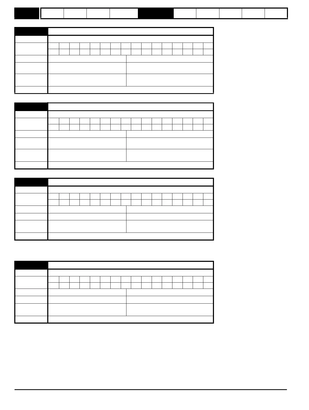
21.17 Speed controller Kp gain
Drive modes Closed-loop vector, Servo
Coding
Bit SP FI DE Txt VM DP ND RA NC NV PT US RW BU PS
4111
Range Closed-loop vector, Servo
0.00 to 6.5535 (1/rad s
-1
)
Default
Closed-loop vector,
Servo
0.0300
0.0100
Normal motor
parameter
Closed-loop vector, Servo Pr 3.10
Update rate Background read
21.18 Speed controller Ki gain
Drive modes Closed-loop vector, Servo
Coding
Bit SP FI DE Txt VM DP ND RA NC NV PT US RW BU PS
2111
Range Closed-loop vector, Servo
0.00 to 655.35 s/rad s
-1
Default
Closed-loop vector,
Servo
0.10
1.00
Normal motor
parameter
Closed-loop vector, Servo Pr 3.11
Update rate Background read
21.19 Speed controller Kd gain
Drive modes Closed-loop vector, Servo
Coding
Bit SP FI DE Txt VM DP ND RA NC NV PT US RW BU PS
5111
Range Closed-loop vector, Servo
0.00000 to 0.65535 s
-1
/ rad s
-1
Default Closed-loop vector, Servo 0.00000
Normal motor
parameter
Closed-loop vector, Servo Pr 3.12
Update rate Background read
21.20 Encoder phase angle
Drive modes Servo
Coding
Bit SP FI DE Txt VM DP ND RA NC NV PT US RW BU PS
11 111
Range Servo 0.0 to 359.9 ° electrical
Default Servo 0.0
Normal motor
parameter
Servo Pr 3.25
Update rate Background read

 Loading...


