Emotron VSB Instruction Manual Chapter 6 Specification of Parameters
Decade:reserved
Hundreds place: bit8 : AI
0: Actual terminal takes effect
1: Virtual terminal takes effect
Virtual terminals simulate actual terminals via communication. Each bit represents one
terminal. When selecting virtual terminal, corresponding bit should be set to 1 in C0-20.
Group C1 Digital O utput
C1-02
Control panel relay
Range: 0 - 99 Factory default: 14
These two parameters define the function of digital output terminal and control panel relay
output
C1-06
Control board relay
Range: 0.0s - 3600.0s Factory default: 0.0s
These two parameters define the time delay of Y output terminal and control board relay output.
C1-08
Enabled state of digital
Range: 000 - 101
Factory default:
Unit's place: Y
0: Positive logic; ON when current passes through
1: Negative logic; ON when no current passes through
Decade: Reversed
Hundreds place: control board relay output
0: Positive logic; ON when there is coil excitation
1: Negative logic; ON when there is no coil excitation
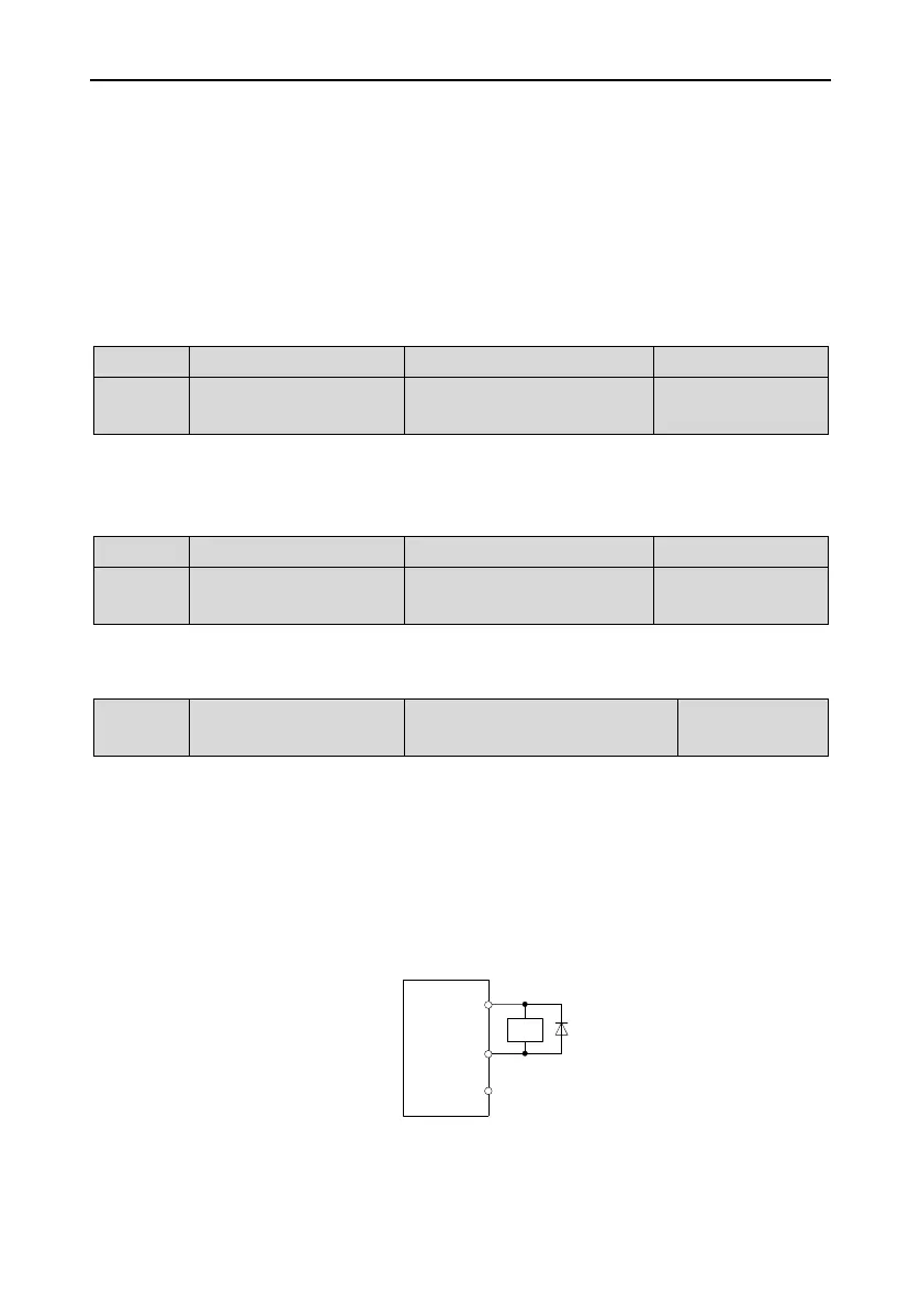
Fig. 6-1 3
- 99 -

 Loading...