Emotron VSB Instruction Manual Chapter 3 Installation and wiring
3.6.1 Main Circuit Terminals
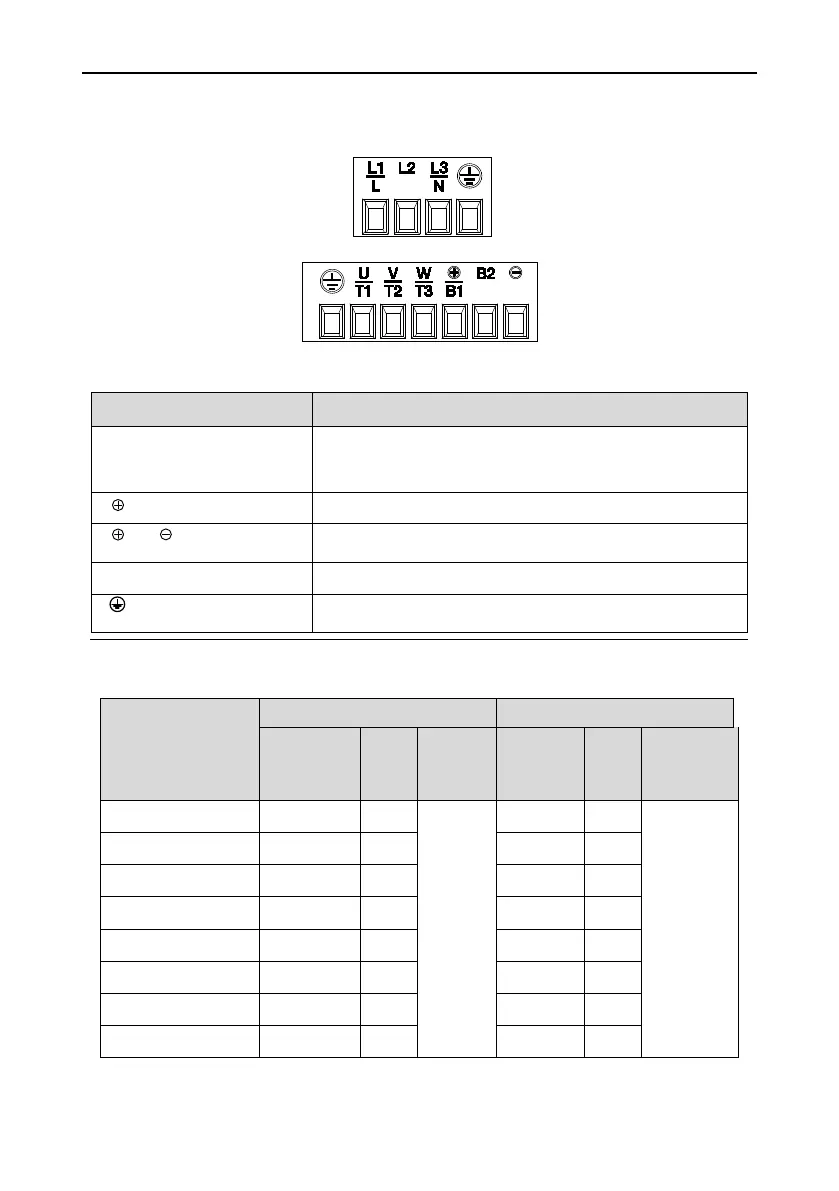
Fig. 3-6 Main circuit terminals
3.6.4 Terminal Screws and Wiring Requirement
Table 3-2 Terminal screws and wiring requirement
Drive model
Power terminal Ground terminal
Cable
requirement
2
Screw
Torque
Nm/Lb-In
Cable
2
Screw
Torque
Nm/Lb-In
VSB23-003-20CNB
2.5 M3.5
0.8 ±0.05/
7 ±0.5
2.5 M3.5
0.8 ±0.05/
7 ±0.5
VSB23-005-20CNB
2.5 M3.5 2.5 M3.5
VSB23-008-20CNB
4 M3.5 2.5 M3.5
VSB23-011-20CNB
6 M3.5 4 M3.5
VSB48-003-20CNB
2.5 M3.5 2.5 M3.5
VSB48-004-20CNB
4 M3.5 4 M3.5
VSB48-006-20CNB
6 M3.5 6 M3.5
VSB48-009-20CNB
6 M3.5 6 M3.5
Terminal marks Designation and function of terminals
L1/L、L2、L3/N
Uniphase/Triphase AC power supply input (connect L1/L,
L3/N when the input is uniphase)
、
Brake resistor wiring terminals
、
DC power supply input terminals
U/T1、V/T2、W/T3 Triphase AC output terminals
Ground terminal PE
- 23 -

 Loading...