Emotron VSB Instruction Manual Chapter 3 Installation and wiring
Instructions of digital o utput term inal
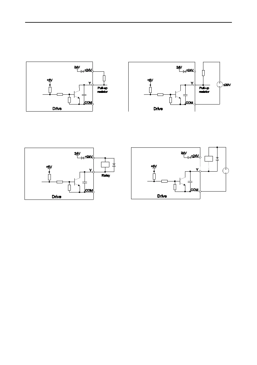
Instructions of Y output terminal
a) Internal power supply b) External power supply
Fig. 3-13 Wiring when Y output with pull-up resistor
a) Internal power supply b) External power supply
Fig. 3-14 Wiring when Y output drive relay
ATTENTION:
When relay coil voltage is lower than 24V, a resistor as voltage divider selected based on
coil impedance should be mounted between relay and output terminal,.
W iring instruction of relay output terminal
RA/RB/RC are relay contacts. RA and RB are normally closed, while RA and RC are
normally open. See parameter C1-02 for details.
ATTENTION:
In case inductive load (e.g. electromagnetic relay or contactor) is to be driven, a surge
voltage absorbing circuit such as RC absorbing circuit, piezoresistor or fly-wheel diode etc.
shall be mounted. Absorbing devices should be mounted close to the end of relay or
contactor.
- 31 -

 Loading...