Emotron VSB Instruction Manual Chapter 6 Specification of Parameters
U0-12 AI input voltage Range: 0.00V - 10.00V
Factory default:
U0-13
Potentiometer input
Range: -10.00V - 10.00V
Factory default:
U0-15 AO output Range: 0.0% - 100.0%
Factory default:
U0-18
Status of digital input
Range: 0 - 7F Factory default: 0
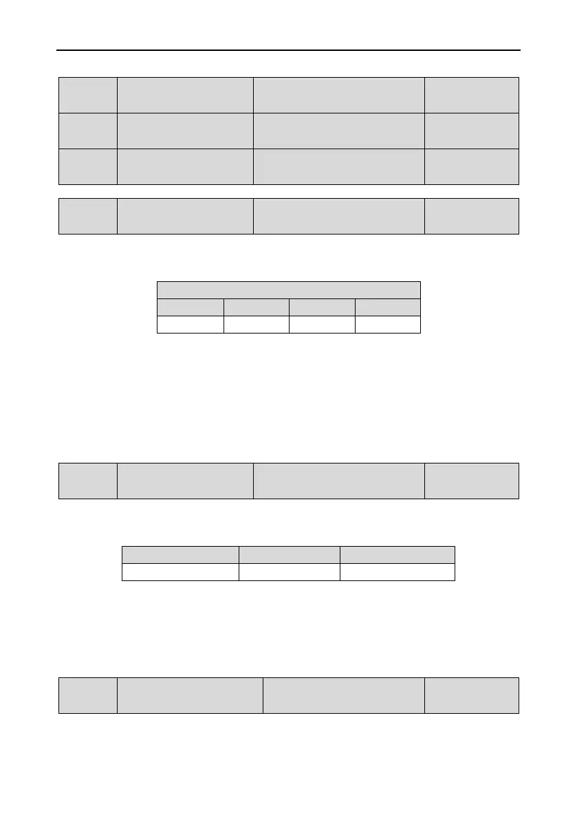
Digital input terminals that correspond to the bits of U0-18 are as shown in Table 6-8:
Table 6-8
0 means terminal input status is OFF, while 1 means terminal input status is ON.
For example:
If 3 (i.e. 0011) is displayed at U0-18, it means the input status of terminals X1 and X2 is ON and
that of the other terminals is OFF.
If 5 (i.e. 0101) is displayed at U0-18, it means the input status of terminals X1 and X3 is ON,
while that of the other terminals is OFF.
U0-19
Status of digital output
Range: 0 - 5 Factory default: 0
Corresponding relationship between digital output terminals and the bits of U0-19 is shown in Table 6-9:
Table 6-9
0 means terminal output status is OFF, while 1 means terminal output status is ON.
For example:
If 4 (i.e. 100) is displayed at U0-19, it means control board relay output is ON while that of the
other terminals is OFF.
U0-20 PID set Range: 0.0% - 100.0%
Factory default:
- 144 -

 Loading...