Emotron VSB Instruction Manual Chapter 3 Installation and wiring
3.8 Control Terminal Specification
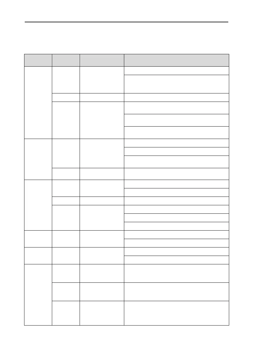
Table 3-3 C ontrol terminal specification
Analog
input
+10V
Analog input
reference voltage
10.3V ±3%
Maximum output current 25mA
The resistance of external potentiometer
should be larger than 400Ω
GND Analog ground Connect with GND interiorly
AI Analog input
0~20mA: input impedance - 500Ω, maximum
input current - 25mA
0~10V: input impedance - 100kΩ, maximum
input voltage - 12.5V
Can be jumped between 0~20mA and 0~10V,
factory default: 0~10V
Analog
output
AO Analog output
0~20mA: impedance - 200Ω-500Ω
0~10V: impedance- 10kΩ
Can be jumped between 0~20 mA and 0
~
~
GND Analog ground Connect with GND interiorly
Digital
+24V +24V
24V±10%
Maximal load 100mA
COM +24V ground Connect with COM interiorly
X1~X4
Digital input
Terminal 1~4
Input: 24VDC, 5mA
Freq range: 0~200Hz
Voltage range: 22V~26V
Digital
output
Y
Open collector
output
Voltage range: 0~24V
Current voltage: 0~50mA
Relay
output
RA/RB/R
C
Control board
relay output
RA-RB: NC; RA-RC: NO
Contact capacity: 250VAC/3A, 30VDC/3A
Terminal
RS485
Interface
485+
differential signal
Rate:
4800/9600/19200/38400/57600/115200bps
485−
differential signal
Maximum distance - 500m (standard network
cable used)
GND
communication
shileded
Connected with GND interiorly
- 26 -

 Loading...