Emotron VSB Instruction Manual Chapter 6 Specification of Parameters
ATTENTION:
Frequency adjustment via ∧ / ∨ on keypad can be cleared through terminal "UP/DOWN (including
∧ / ∨ key) adjustment clear " . Refer to C0-01 - C0-08 for details.
1: Digital setting (b0-02) + terminal UP/DOWN adjustment
When the drive is powered up, the value of b0-02 is taken as the master frequency command.
This frequency can be adjusted via “terminal UP” and “terminal DOWN” no matter the drive is
running or in stop.
When this parameter value is selected, following parameter setting should be performed:
1) Set the two digital input terminals to "terminal UP" and "terminal DOWN" respectively.
Refer to C0-01 - C0-08 for further information.
2) Set terminal UP/DOWN frequency change step size (C0-18).
3) Set C0-17 (terminal UP/DOWN frequency adjustment treatment).
ATTENTION:
Frequency adjustment via terminal UP and DOWN can be cleared through terminal "UP/DOWN
(including ∧ / ∨ key) adjustment clear" . Refer to C0-01 - C0-08 for details.
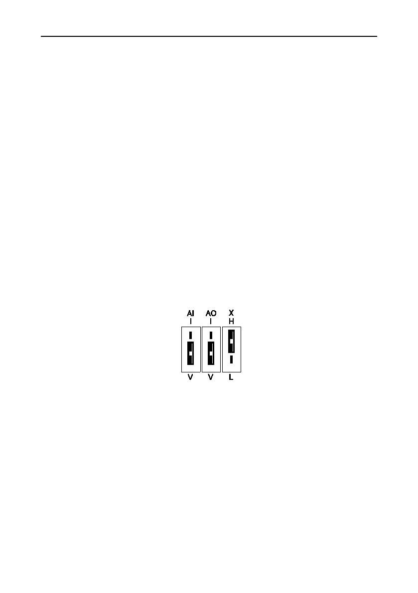
2: Analogue input AI
(0 - 10V) voltage input and (0 - 20mA) current input are optional for AI, which can be selected
using toggle switch AI on control board.
Fig. 6-2
Refer to specification of C2-00 - C2-12 for corresponding relation between analogue input
and output frequency.
See parameter Group C4 for automatic correction of analogue quantity input.
3: Keypad potentiometer input
Keypad potentiometer input is 0~5V input.
Refer to detailed description of C2-00~C2-20 for corresponding relation between analog
value and frequency.
See parameter group C4 for automatic correction of analog input
6: Process PID output
Command frequency is determined by process closed-loop PID computation result. See
parameter Group F0 for details.
- 74 -

 Loading...