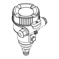
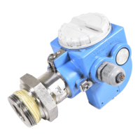
Cerabar M PMC51, PMP51, PMP55
18 Endress+Hauser
Link settings
Slot time 4
Min. Inter PDU delay 12
Max. response delay 40
Transducer Blocks
Block Content Output values
TRD1 Block Contains all parameters related to the
measurement
• Pressure or level (channel 1)
• Process temperature (channel 2)
• Measured pressure value (channel 3)
• Max. pressure (channel 4)
• Level before linearization (channel 5)
Diagnostic Block Contains diagnostic information Error code via DI channels (channel 10 to 15)
Display Block Contains parameters to configure the onsite
display
No output values
Function blocks
Block Content Number
of blocks
Execution
time
Functionality
Resource Block The Resource Block contains all the data that uniquely identify the device. It is an
electronic version of a nameplate of the device.
1 enhanced
Analog Input
Block 1
Analog Input
Block 2
The AI Block receives the measuring data from the Sensor Block, (selectable via a
channel number) and makes the data available to other function blocks at its output.
Enhancement: digital outputs for process alarms, fail safe mode.
2 25 ms enhanced
Digital Input
Block
This block contains the discrete data of the Diagnose Block (selectable via a channel
number 10 to 15) and provides them for other blocks at the output.
1 20 ms standard
Digital Output
Block
This block converts the discrete input and thus initiates an action (selectable via a
channel number) in the DP Flow Block or in the im TRD1 Block. Channel 20 resets the
counter for max. pressure transgressions value.
1 20 ms standard
PID Block The PID Block serves as a proportional-integralderivative controller and is used almost
universally for closed-loop-control in the field including cascade and feedforward. Input
IN can be indicated on the display. The selection is performed in the Display Block
(DISPLAY_MAIN_LINE_CONTENT).
1 40 ms standard
Arithmetic Block This block is designed to permit simple use of popular measurement math functions.
The user does not have to know how to write equations. The math algorithm is selected
by name, chosen by the user for the function to be performed.
1 35 ms standard
Input Selector
Block
The Input Selector Block facilitates the selection of up to four inputs and generates an
output based on the configured action. This block normally receives its inputs from AI
Blocks. The block performs maximum, minimum, average and ‘first good’ signal
selection. Inputs IN1 to IN4 can be indicated on the display. The selection is performed
in the Display Block (DISPLAY_MAIN_LINE_1_CONTENT).
1 30 ms standard
Signal
Characterizer
Block
DThe Signal Characterizer Block has two sections, each with an output that is a non-
linear function of the respective input. The non-linear function is generated by a single
look-up table with 21 arbitrary x-y pairs.
1 40 ms standard
Integrator Block The Integrator Block integrates a variable as a function of the time or accumulates the
counts from a Pulse Input Block. The block may be used as a totalizer that counts up
until reset or as a batch totalizer that has a setpoint, where the integrated or
accumulated value is compared to pre-trip and trip settings, generating a binary signal
when the setpoint is reached.
1 35 ms standard

 Loading...
