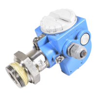
Cerabar M PMC51, PMP51, PMP55
Endress+Hauser 47
T
p
T
a
+32
+80
40
+185
113
200
100
−70
300
392
392
+32
−94
572
T
a
[°C]
[°F]
[°C][°F]
− −40 25
− −40 22
0
0
T
p
A0028227
Pressure specifications
L
WARNING
The maximum pressure for the measuring device depends on the lowest-rated element with
regard to pressure.
‣
For pressure specifications, see the "Measuring range" section and the "Mechanical construction"
section.
‣
Only operate the measuring device within the prescribed limits!
‣
The Pressure Equipment Directive (2014/68/EU) uses the abbreviation "PS". The abbreviation "PS"
corresponds to the MWP (maximum working pressure) of the measuring device.
‣
MWP (Maximum Working Pressure): The MWP (maximum working pressure) is specified on the
nameplate. This value refers to a reference temperature of +20 °C (+68 °F) and may be applied to
the device for an unlimited time. Observe the temperature dependency of the MWP. For the
pressure values permitted at higher temperatures for flanges, please refer to standards EN
1092-1 (with regard to their stability-temperature property, the materials 1.4435 and 1.4404
are grouped together under EN 1092-1; the chemical composition of the two materials can be
identical.), ASME B 16.5a, JIS B 2220 (the latest version of the standard applies in each case).
‣
OPL (Over Pressure Limit = sensor overload limit): The test pressure corresponds to the over
pressure limit of the sensor and may only be applied for a limited time period so that no
permanent damage develops. In the case of sensor range and process connection combinations
where the over pressure limit (OPL) of the process connection is smaller than the nominal value
of the sensor, the device is set at the factory, at the very maximum, to the OPL value of the
process connection. If you want to use the entire sensor range, select a process connection with a
higher OPL value.
‣
Oxygen applications: In oxygen applications, the values for p
max
and T
max
for oxygen applications
may not be exceeded → 42 .
‣
Devices with ceramic process isolating diaphragm: Avoid steam hammering! Steam hammering
can cause zero point drift. Recommendation: Residue (water droplets or condensation) may
remain on the process isolating diaphragm following CIP cleaning and can result in local steam
hammering the next time steam cleaning takes place. In practice, drying the process isolating
diaphragm (e.g. by blowing off excess moisture) has proven to be a successful way of avoiding
steam hammering.

 Loading...
