Installing the K Chassis
Enterasys K-Series K6 Chassis Hardware Installation Guide 3-11
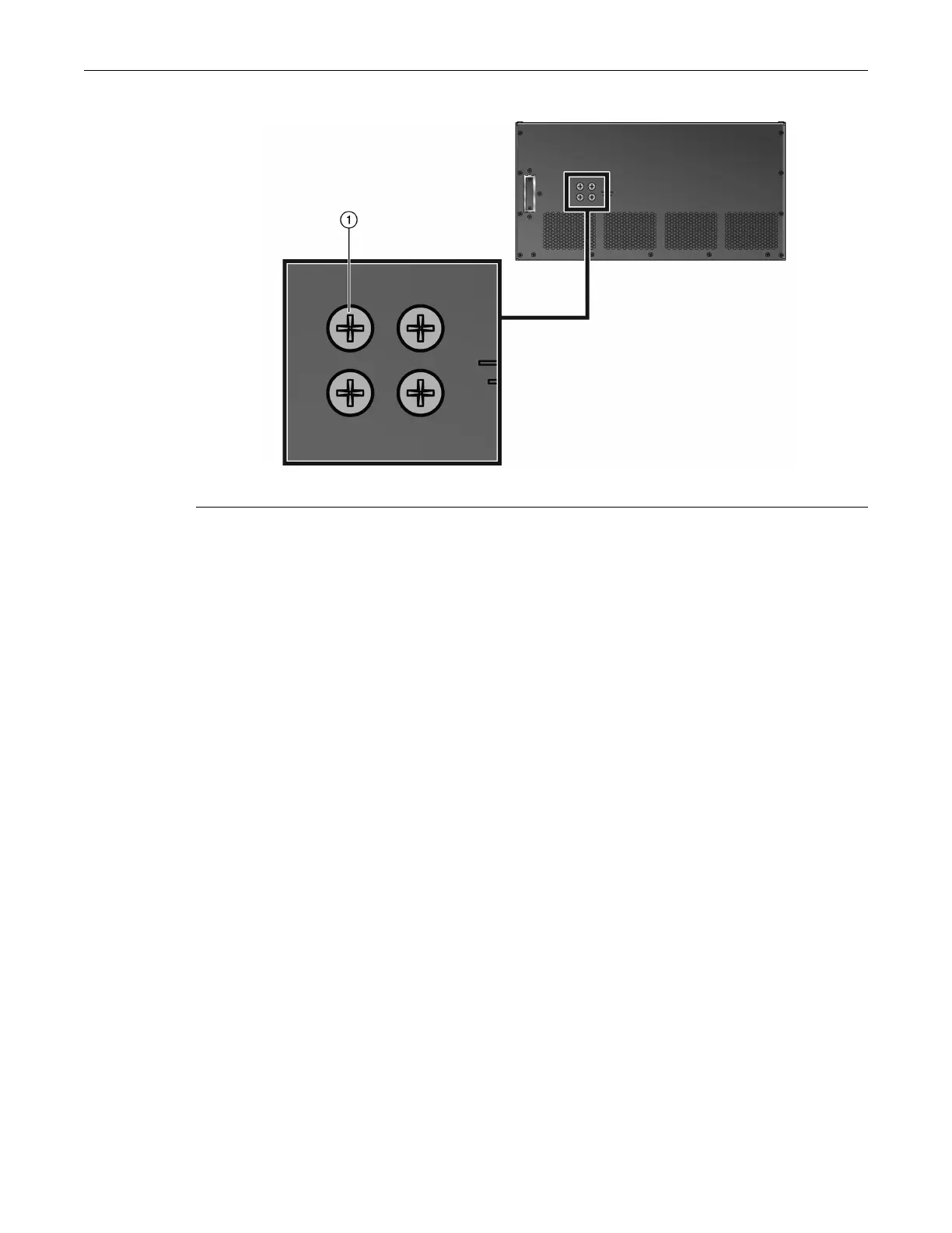
Figure 3-10 Telcordia GR-1089 Grounding Hole Pattern
Alternategroundingrequirementswhenaconnectionisneededbetweenthechassisandthe
enclosuremetalwork,anearbypointontheCentralOffice(CO)Groundsystem,orearthground.
Theconnectionismadeusingoneormoregroundingwires(asneeded)fabricatedfroman8AWG
(6
2
mm)strandedcopperwire.Tofabricateandinstallagroundingwire,proceedasfollows:
1. Cutan8AWG(6
2
mm)stranded‐copperwiretolength,longenoughtoreachfromthe
groundinglocationofthechassistotheselectedgroundinglocationontheCO Ground,earth
ground,orenclosuremetalwork.
2. Installalistedtwo‐holecompression‐typeconnectoronbothendsofthegroundingwire.
3. Applyasuitableantioxidanttothe
chassisgroundinglocationandunpainted su rface
groundinglocationontheCOGroundorenclosuremetalwork.
4. Connectonegroundcabletwo‐holeconnectortothechassisusingtwoofthe1/4‐20screws
shippedwiththechassis.Connectthetwo‐holeconnectorattheotherendofthecabletothe
CO
Groundorenclosuremetalworkusinguser‐suppliedscrews.
5. Torquescrewsto67inchpounds(±5%).
NationalDeviations:
•InNorway,Sweden,andFinland,thesameprocedurecanbeusedforapermanentprotective
earthgroundconnectionasrequiredbytheirnationaldeviationtoIEC60950,Section5.1.7.
•InDenmark,thechassismust
beinstalledutilizingaTypeBgroundedplug.
1 Ground screws