Connecting the Fabric Card and Line Card to the Network
Enterasys K-Series K6 Chassis Hardware Installation Guide 3-29
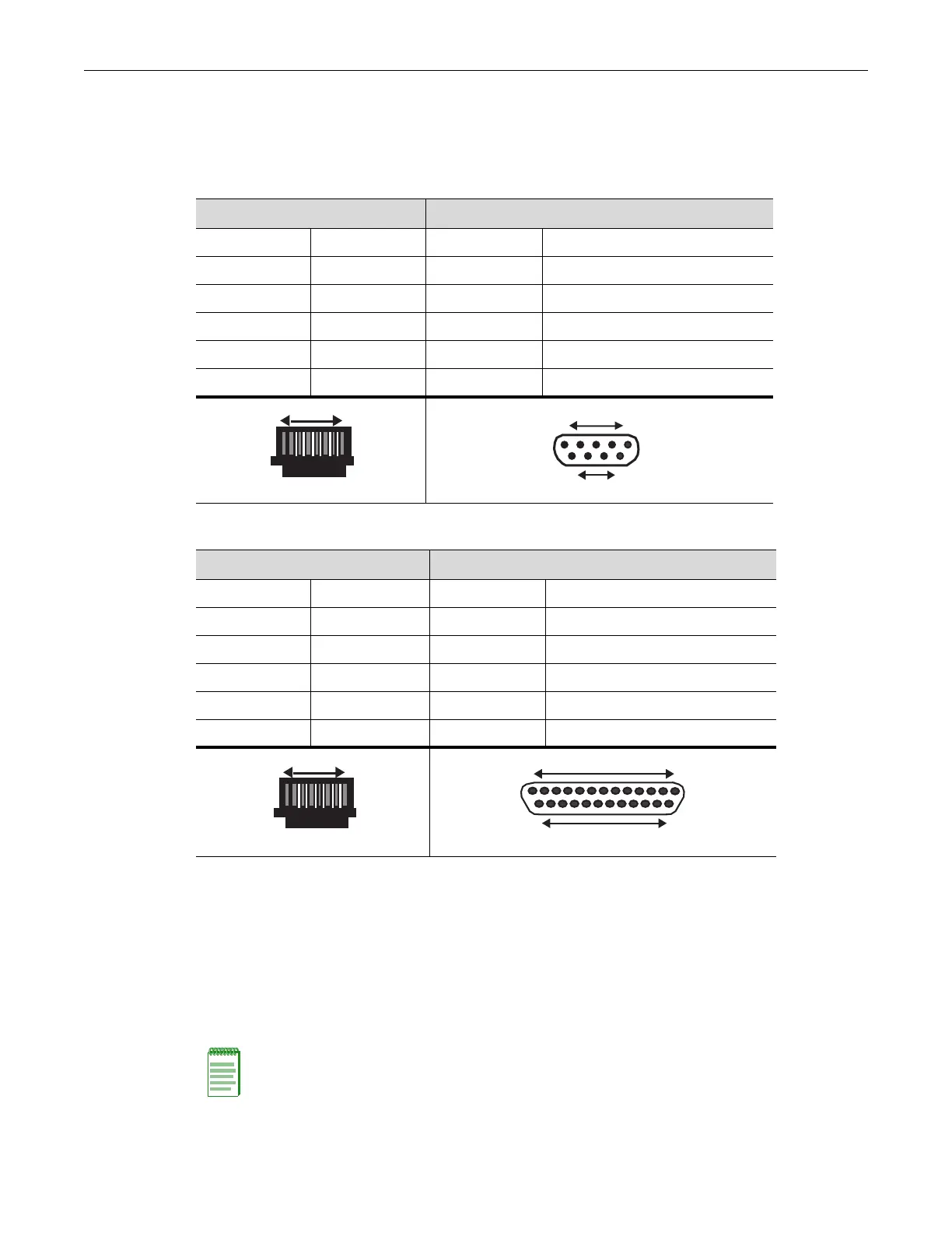
Adapter Wiring and Signal Assignments
Table 3‐3showstheCOMportadapterwiringandsignaldiagram.Table 3‐4showstheVTseries
portadapterwiringandsignaldiagram.
Connecting the Fabric Card and Line Card to the Network
Thissectionprovidesproceduresforconnectingthefoll owing:
• Category5unshieldedtwistedpair(UTP)segmentstotheK‐Serieslinecards
•SFPandSFP+pluggabletransceiverstotheK‐Serieslinecards
•SFP+pluggabletransceiverstotheK‐Seriesfabriccard
Table 3-3 COM Port Adapter Wiring
RJ45 DB9
Pin Conductor Pin Signal
1 Blue 2 Receive (RX)
4 Red 3 Transmit (TX)
5 Green 5 Ground (GRD)
2 Orange 7 Request to Send (RTS)
6 Yellow 8 Clear to Send (CTS)
Table 3-4 VT Series Port Adapter Wiring
RJ45 DB25
Pin Conductor Pin Signal
4 Red 2 Transmit (TX)
1 Blue 3 Receive (RX)
6 Yellow 5 Clear to Send (CTS)
5 Green 7 Ground (GRD)
2 Orange 20 Data Terminal Ready
RJ45 Connector (Female)
Pins
81
69
DB9 Connector
Female
15
Pins
RJ45 Connector (Female)
Pins
81
DB25 Connector (Female)
Pins
25
14
13 1
Note: If the K-Series module is being installed in a network using Link Aggregation, there are rules
concerning the network cable and port configurations that must be followed for Link Aggregation to
operate properly. Before connecting the cables, refer to the Enterasys K-Series Configuration
Guide for the configuration information. For details on how to obtain manuals, refer to “Related
Documents” on page xvi.