Connecting to the Fabric Card COM Port for Local Management
Enterasys K-Series K6 Chassis Hardware Installation Guide 3-27
1. Plugoneendofeachpowercord(suppliedwiththepowersupply)intotheACpowersocket
onthefrontpanelofthepowersupplies.
2. Plugeachofthepowercordsintoseparatededicated15A/120Vacreceptacles.
3. EnsurethattheACOKandDCOKLEDsoneachpowersupply
aregreen.
FormoreinformationonthepowersupplyLEDs,referto“K ‐AC‐PS‐1400WPowerSupply
LEDs”onpage 4‐5.
4. Ensurethatallfansinthefantrayareoperatingproperlywhenpowerisreceivedfromthe
powersupplies.Ifthefansareoperatingproperly,theFANLED
onthefabriccardwillbe
green.
Ifyouexperienceanyproblemswiththisinstallation,contactEnterasys Networksforassistance.
Connecting to the Fabric Card COM Port for Local Management
ThissectiondescribeshowtoinstallaUTPcablewithRJ45connectorsandoptionaladaptersto
connectaPCorVTseriesterminaltoanEnterasys NetworksdevicetoaccessLocalManagement.
Thissectionalsodetailsadapterpinoutassignments.
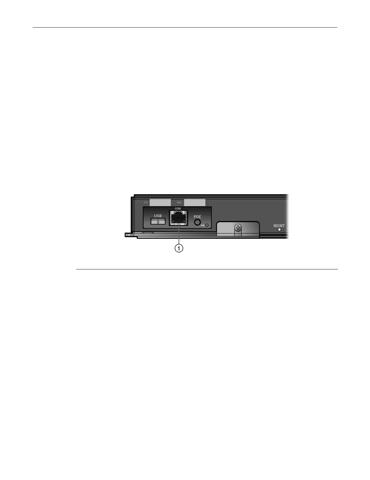
Figure 3-28 Fabric Card COM Port
What Is Needed
Thefollowingisalistofthepartsthatmaybeneededdependingontheconnection:
•RJ45‐to‐DB9femaleadapter(suppliedwiththe K6chassis)
•UTPcablewithRJ45connectors(suppliedwiththeK6chassis)
•RJ45‐to‐DB25femaleadapter(customer‐supplied)
UsingtheUTPcablewithRJ45connectorsandtheRJ45
‐to‐DB9adapter,youcanconnecttoaK6
chassisRJ45COMporttoaPCrunningaVTseriesemulationsoftwarepackage.
UsingtheUTPcableandanoptionalRJ45‐to‐DB25femaleadapter,youcanconnecttoaK6chassis
RJ45COMporttoaVTseriesterminalor
VTtypeterminalsrunningemulationprogramsforthe
VTseries.
Connecting to a PC or Laptop
ToconnectaPCorlaptoprunningtheVTterminalemulationtothefabriccardCOMport:
1. ConnecttheRJ45connectoratoneendofthecabletotheCOMportonthefabriccard.
2. PlugtheRJ45connectorattheotherendofthecableintotheRJ45‐to‐DB9
adapter.
1 COM port