LEDs
Enterasys S-Series Stand Alone (SSA) Hardware Installation Guide 3-3
System LEDs
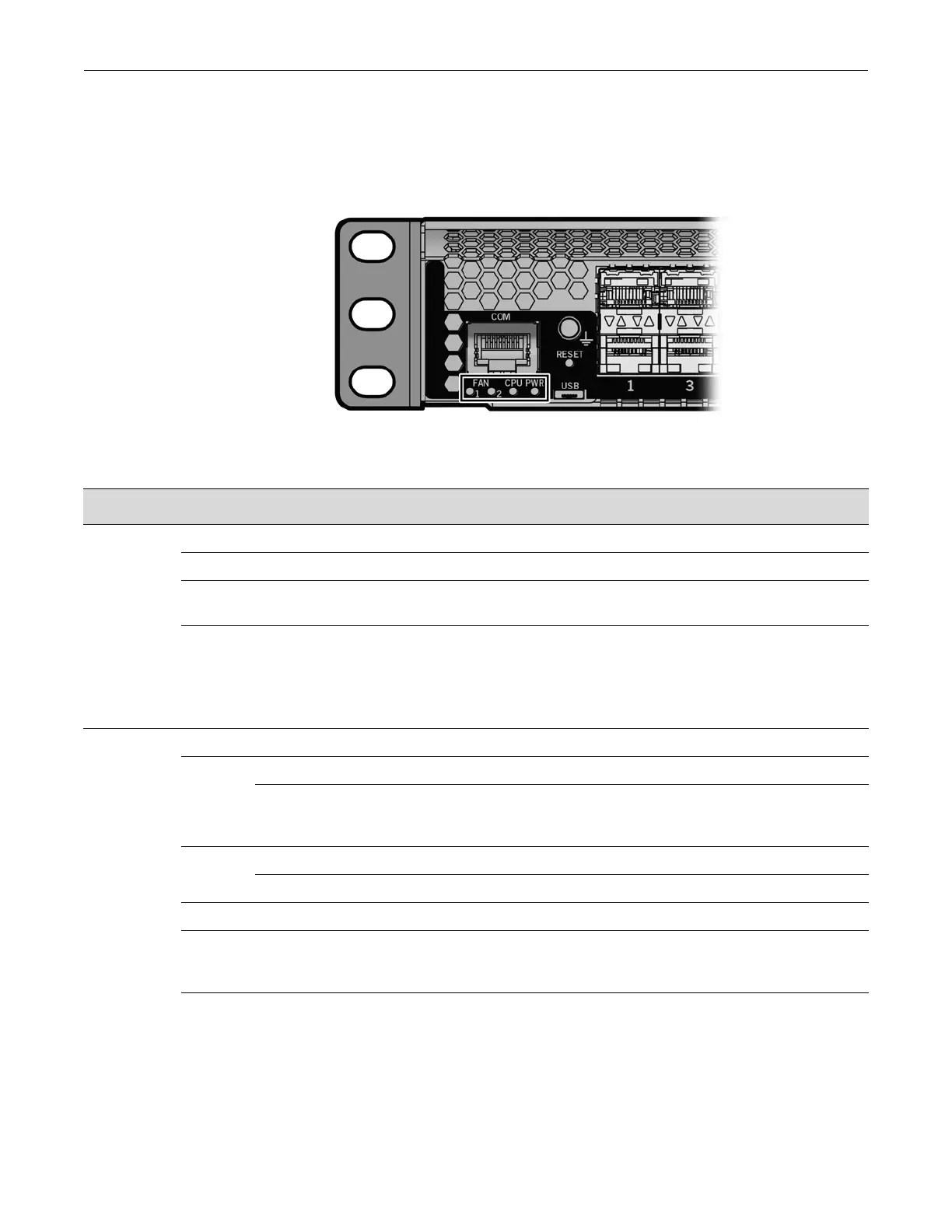
Figure 3-3 shows the SSA system LEDs. The two left LEDs are separately labeled for fan modules
1 and 2.
Figure 3-3 SSA System LEDs
Table 3-2 describes the LED indications for the system LEDs and provides recommended actions.
Table 3-2 System LEDs
LED Color State Recommended Action
FAN 1 and 2 Off Fans are off or booting up. None.
Green All fans are operating normally. None.
Amber One fan has failed. Replace the failed fan. See “Replacing
the SSA Fan Module” on page 3-6.
Red One or more of the following conditions has occurred:
• Temperature is out of range.
• The fan controller has failed.
• Both fans have failed.
Use the show system CLI command to
check the exact condition of the fans.
If fans have failed, replace the fan
module. See “Replacing the SSA Fan
Module” on page 3-6.
CPU Off Power off. Ensure chassis has adequate power.
Amber Blinking. Device in bootup process. None.
Solid. Testing. If the LED remains amber for several
minutes, contact Enterasys Networks for
technical support.
Green Blinking. Image starts running. None.
Solid. Functional. None.
Red Solid. Processor in reset. None.
Green
and
Amber
Blinking. Indicates that the SSA switch is in the
process of shutting down.
None. This state is activated when the
RESET button is pressed for less than
1 second to start an orderly shutdown.
Amber
and off
Alternating (67% on, 33% off). Indicates a shutdown
is complete. The indication will hold for 60 seconds
then automatically restart.
While in this state, you have 60 seconds
before the SSA switch will reboot.

 Loading...