Installing the Adapter Plates
C-4 Optional Rack Mount Rail Kit Installation
The SSA switch can be configured for air intake on either the chassis switch I /O port side or the
power supply side. Adapter plate installation must align the adapter plate ears with the air intake
side of the chassis.
If you have not verified the power supply and fan module air flow for the chassis you are
installing, see “Power Supply Air Flow and Switch Fan Module Air Flow” on page 2-4 for
information on determining air flow direction for your chassis before installing the adapter plates.
See “Reversing the Fan Module Air Flow” on page 2-5 if the current fan module air flow direction
does not match the intended chassis air flow direction.
To install the adapter plates:
1. Place the adapter plates on each side of the chassis with the ear end toward the air intake side
of the chassis, ear flange pointing away from the chassis. Figure C-2 shows the correct
orientation for a chassis with air flow from switch I/O port side to power supply side.
2. Align either the flush mount adapter plate screw holes (Callout 2) or the appropriate recess
mount adapter plate screw holes with the three chassis screw holes on each side of the chassis.
Callout 3 identifies the screw holes used to recess the chassis by .5, 1.0, or 1.5 inches
3. Insert and tighten three of the six 6-32 flat head screws that come with the mounting kit in
three places on each side of the chassis.
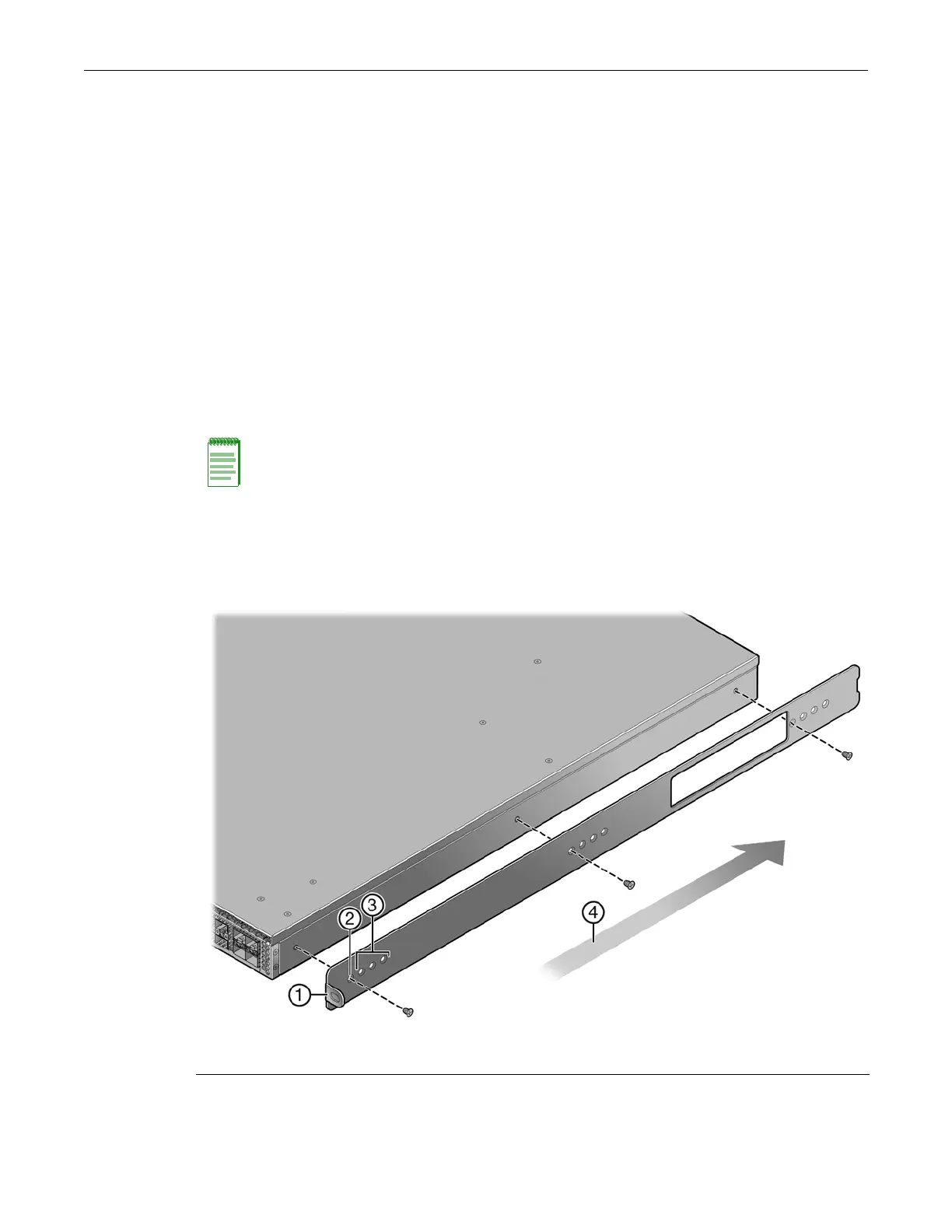
Figure C-2 Installing the Adapter Plates
Note: When recess mounting, use care that the installation does not result in openings above and
below the chassis face at the inlet side that allow for hot air recirculation from the exhaust side of
the rack or cabinet. This is especially the case for a cabinet with enclosed sides where the cold and
hot aisles are meant to be isolated.
1 Adapter plate (ear side) 3 Recess mount adapter plate screw holes (1.5 in.)
2 Flush mount adapter plate screw hole 4 Air flow direction
 Loading...