SC-F2000 Revision C
DISASSEMBLY & ASSEMBLY Disassembly and Assembly Procedure 113
Confidential
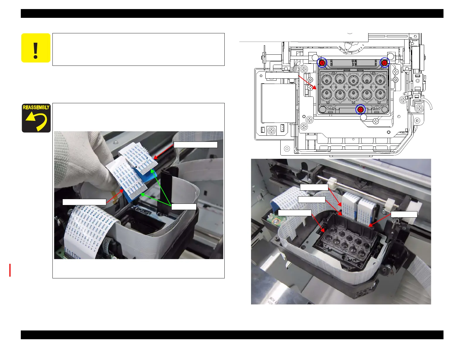
9. Remove the three screws, and remove the PRINT HEAD.
D) Silver M2.5x6 P-tite screw (Bit No.1): 3 pcs
10. Disconnect the four FFCs from the connectors of the PRINT HEAD.
Figure 3-63. Removing the PRINT HEAD
In the next step, Do not touch the surface of the head nozzle.
Make sure to connect the FFCs to the correct connectors.
When connecting the FFCs, make sure the terminals of CN2
and CN4 are facing outwards.
Installing the PRINT HEAD, attach the sponges, film (1) and
film (2) of the INK MIST COVER ASSY. (p114)
Head FFC (CN4)
Head FFC (CN2)
terminals
PRINT HEAD
HEAD FFC
Connectors
Connectors
 Loading...


