SC-F2000 Revision C
DISASSEMBLY & ASSEMBLY Disassembly and Assembly Procedure 128
Confidential
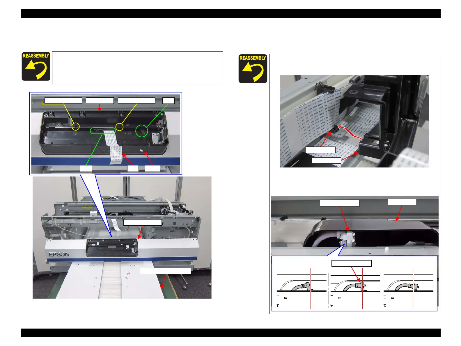
18. Release the FFC and the cable from the holes on the Panel Cover, and place the
Front Cover Assy on the Table Feed Mechanism.
Figure 3-92. Removing the Front Cover Assy (2)
19. Remove the three screws, and remove the Tube Cover.
C) Silver M3x6 Cup S-tite screw: 3 pcs
Pay attention to the positioning points (See Figure 3-92).
FFC Cable
Panel Cover
Positioning point
Hole
Positioning point
Hole
Table Feed Mechanism
Front Cover Assy
Pay attention to the positioning points (See Figure 3-93).
Clamp the Cable Holder with the Tube Cover.
Make sure that the Tube Fixing Plate is not tilted. if the result is
NG, adjust the position of the Tube Fixing Plate by the screw C
shown in Figure 3-102.
f
 Loading...


