SC-F2000 Revision C
DISASSEMBLY & ASSEMBLY Disassembly and Assembly Procedure 144
Confidential
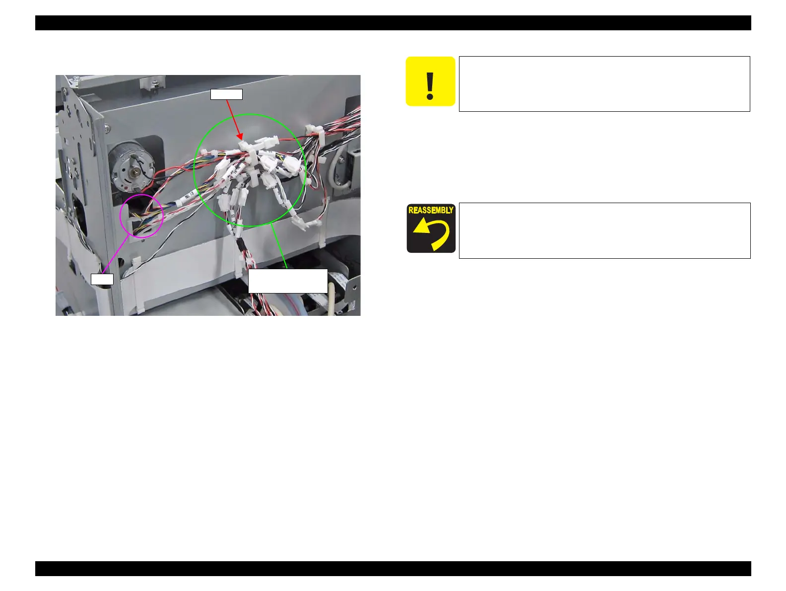
8. Pull the cables in the hole on the frame.
Figure 3-111. Removing the relay connector
9. Remove the Waste Ink Tube from the DUCT TUBE ASSY.
10. Pull the Waste Ink Tube in the hole on the frame.
11. Remove the two screws that secure the PUMP CAP ASSY.
B) Silver M3x6 Cup S-tite screw: 2 pcs
Relay connectors
(No.19, No.23, No.26)
Hole
Clamp
When the Waste Ink Tube is removed at the following step, waste
ink may drip off from the tube. Prepare a waste cloth or the like in
advance and be careful not to contaminate the surroundings.
Pay attention to the positioning point (See Figure 3-112).
 Loading...


