SC-F2000 Revision C
DISASSEMBLY & ASSEMBLY Disassembly and Assembly Procedure 143
Confidential
3.4.5.11 PUMP CAP ASSY
1. Remove the PRINTER COVER. (p72)
2. Remove the RIGHT HOUSING PLATE. (p74)
3. Remove the RIGHT COVER ASSY. (p88)
4. Unlock the CR UNIT. (p69)
5. Remove the screw, and remove the Maintenance Cover.
A) Silver M3x6 Cup S-tite screw: 1 pcs
Figure 3-110. Removing the Maintenance Cover
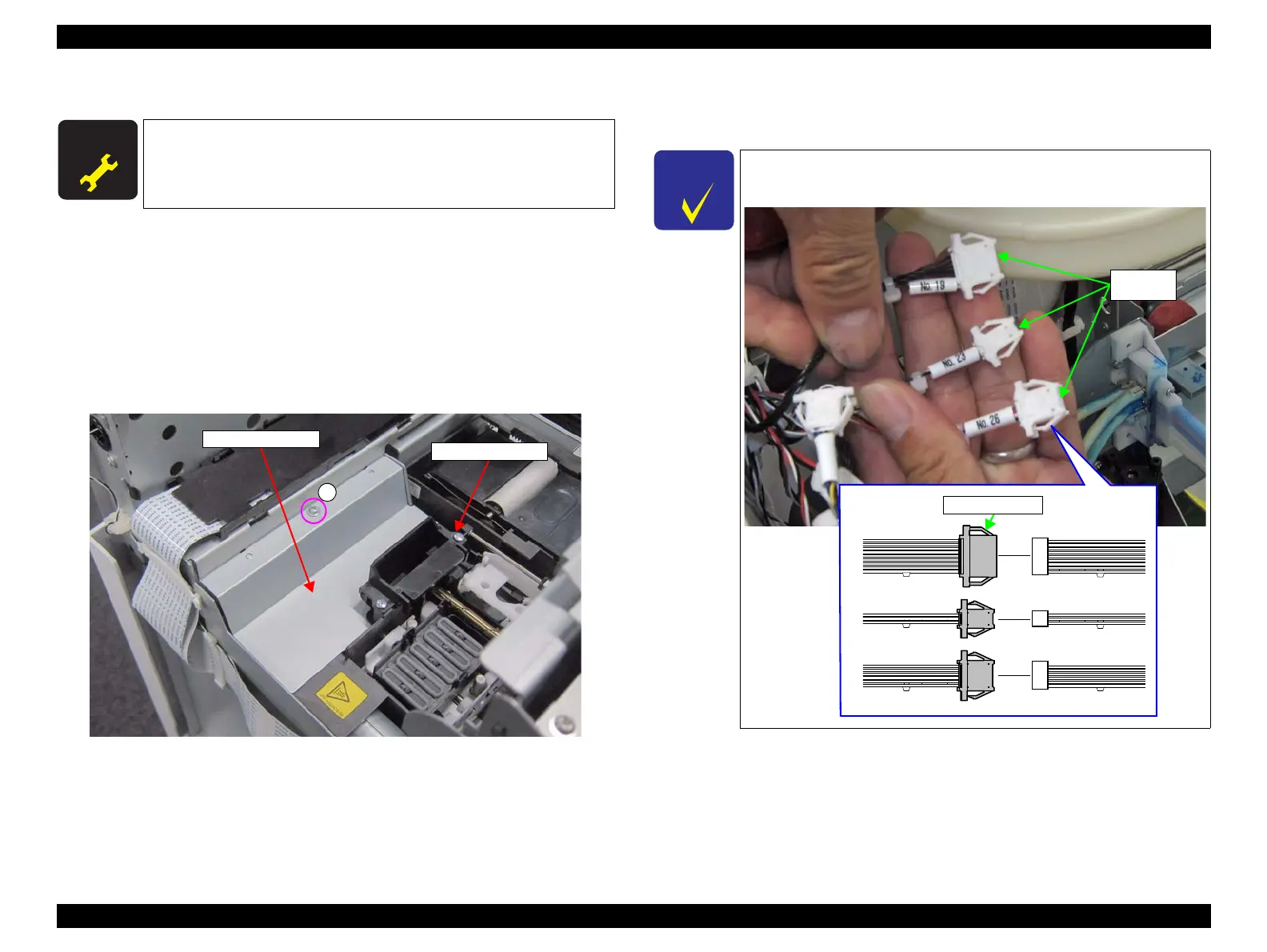
6. Release the cables from the clamp.
7. Disconnect the cables from the relay connectors (No.19, No.23, No.26).
A D J U S T M E N T
R E Q U I R E D
When replacing this part, refer to “4.1.2 Adjustment Items and
the Order by Repaired Part” (p194) and make sure to perform the
specified operations including required adjustment.
A
PUMP CAP ASSY
Maintenance Cover
Leave the relay connectors at the main body side to reuse them.
Confirm the relay connectors to disconnect the cables.

 Loading...


