SC-F2000 Revision C
DISASSEMBLY & ASSEMBLY Disassembly and Assembly Procedure 162
Confidential
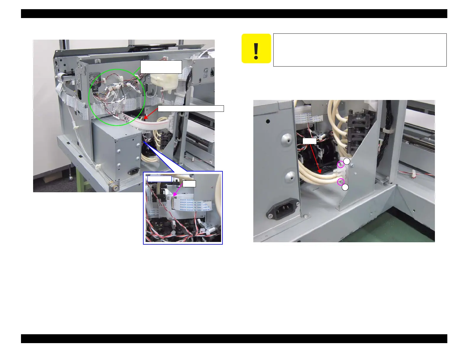
Figure 3-125. Removing the RIGHT INK HOLDER ASSY (1)
14. Remove the two screws, and remove the tube.
A) Silver M3x10 Bind machine screw: 2 pcs
Figure 3-126. Removing the Tube
15. Remove the four screws, and remove the RIGHT INK HOLDER ASSY.
B) Silver M3x6 Cup S-tite screw: 1 pcs
C) Silver M3x6 Cup S-tite screw: 1 pcs
D) Silver M3x6 Cup S-tite screw: 2 pcs
Relay connectors
(No.4, No.6, No.8)
RIGHT INK HOLDER ASSY
When the Tube is removed at the following step, ink may drip off
from the tube. Prepare a waste cloth in advance and be careful not
to contaminate the surroundings.
 Loading...


